My twist locks at the rear of the amp have been removed so I thought I could connect the speaker cable directly to to power bord or somewhere closer to the power amp section. I don't understand the schematic drawings so naw I'm lost!. There must be something at the power bord to connect speakers A and B speakers or somewhere after eg at the volume knob or speaker selector switch. Please help I love this underrated beauty it just dilivers what you need.

You insert a bare stripped wire into the connector and twist it to tighten.
If there are just holes now, you could install banana sockets or 5 way binding posts,
depending on whether they fit the holes.
Do not plug in, or turn on, this receiver until the speaker outputs are properly connected.
Measure the hole diameter. Also post a photo of the inside where the holes are located.
Not a good idea to solder wires directly to the board, this will cause mechanical problems
and possibly electrical problems if the wires get loose.
Last edited:
+1 on the 5-way bonding posts. Guessing the originals were removed because the 10 gauge speaker wire didn't fit. 
jeff
jeff
Also measure the distance between the adjacent holes, center to center.
You may have to enlarge the holes for 5 way binding posts,
but single banana sockets may fit the holes as-is.
All connectors have to be insulated of course, like these.
https://www.amazon.com/CESS-Black-Banana-Female-Socket/dp/B07D52R7TL/ref=sr_1_3
You may have to enlarge the holes for 5 way binding posts,
but single banana sockets may fit the holes as-is.
All connectors have to be insulated of course, like these.
https://www.amazon.com/CESS-Black-Banana-Female-Socket/dp/B07D52R7TL/ref=sr_1_3
Last edited:
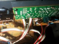
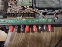
This is what o got, van I splice the speaker cable to the cable where I'm holding up with myscrew driver? Thay go to the selector knob and to where the old connectors used to be?. I have to go for naw but hope to continue tomorrow. Thanks
Attachments


Big holes, so it's likely that 5 way binding posts will fit.
But don't connect the speaker wires internally.
What diameter are the holes?
But don't connect the speaker wires internally.
What diameter are the holes?
On the image the last one the 319.6 kb (size) of file you should be able to see 4 sets of
2 holes, that's were the twist locks where solder'd to and the 4 cables to the right go
directly to the selector switch as do the other 4 you can see under my hand with the screwdriver.
2 holes, that's were the twist locks where solder'd to and the 4 cables to the right go
directly to the selector switch as do the other 4 you can see under my hand with the screwdriver.
I had to do this to my Technics SE-A7. As several of the twist locks had gotten stuck. It's a slim chassis so it's hard to get a good pic. But if you look hard enough in the first pic you can see short wires going from the binding posts to the PCB above them, where the original twist locks were mounted to. I had it easy. It looks like you're going to have to remove the board from the chassis to be able to solder wires to the board. You will also need fender washers as the holes are too big for 5 way binding posts
Attachments

Can I not splice the cable anywhere as show in pics above? To make thingsc eazy. I have the schematic but don't know how to read it!!
Looking at the schematic again, the selector board only switches the (+) output. You will still need to find somewhere to attach the (-) return.
I think I can splice 4 cords. too. Goes to negative and all 4 to positive. I this the PIC you want I will draw it so its more clear.
Attachments
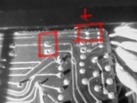
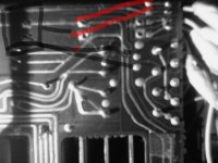
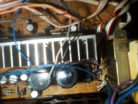
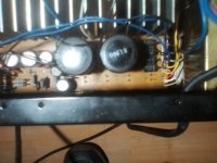
It's hard to make out where in the circuit the last two pics are of. And while you could find some "ground" point to attach to. It's often recommended to have the speaker (-) return go straight to the power supply. Sansui laid the board out so the original speaker posts were right next to the power supply filter caps. I think the optimal thing to do would be to remove the main board and attach the wires to the original locations.
https://www.opweb.de/english/company/Sansui/R-50
This will take you to the bord/schematics im hopefully optimistic there is somewhere I could splice the speaker cable into the system before the old twist locks were attached. Fingers crossed!
This will take you to the bord/schematics im hopefully optimistic there is somewhere I could splice the speaker cable into the system before the old twist locks were attached. Fingers crossed!
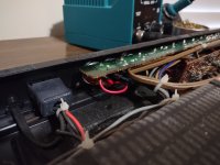
On the schematics there is a wire going from the speaker selector board to the main board that serves as the ground line for the headphone jack. Connection "32". If you can identify that wire, that may be your best bet at a simple splice in connection. I just noticed the RCA jacks have also been removed from your unit. Do you plan on using just the tuner?
Thanks for the advice. .the RCA"s have just been removed to get access. It's the bedroom system, I'll show you a picture later on. My main system is basically 2 amps that I swap arround. Vintage only, Sony ta1144 seriously nice amp and Pioneer sx410 valve receiver that is really special. My speakers are the pro9 transmission line "criss Rogers" design look just like Cambridge audio r50 but I haven't herd those... but mine sound amazing. I've had loads of amps and speakers but these are just perfect for me. I'll picture those also. Thanks man!!!
- Home
- Amplifiers
- Solid State
- Need help to connect speakers to my Sansui R50 reciever