I have a TSE 300b amplifier which has suddenly started to sound bad. In the attached image you can see that I have measured the output, and there is clearly something wrong.
I have measured the signal at the following places in the amplifier:
1. Signal on RCA input = ok
2. Signal just before the input tube = ok
3. Signal after the coupling cap = ok
4. Signal after output transformer = BAD (attached image)
Could this be due to a bad filament regulator (Sharp PQ5EV5 voltage regulator) or the STPS30L30CT dual schottky rectifier?
What is the signal at the 300B grid? The amp is obviously clipping on one side. If the grid drive to the 300B is OK, then the problem is likely in the output. If the filament supply is shot, then the tube might not have sufficient emission to pull down properly. Check filament voltage?
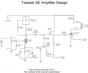
Please post your exact schematic, if different from that below, with measured DC voltages listed.
Did you adjust the two controls? Has the circuit ever worked properly, or is this a new circuit?
Did you adjust the two controls? Has the circuit ever worked properly, or is this a new circuit?
Attachments
Last edited:
Blue is grid on the 300b tube
Red is output after output transformer
One channel, but it is the same on the other channel too.

Red is output after output transformer
One channel, but it is the same on the other channel too.
give me just 10 min..Please post your exact schematic, if different from that below, with measured DC voltages listed.
Did you adjust the two controls?
Please post your exact schematic, if different from that below, with measured DC voltages listed.
Did you adjust the two controls? Has the circuit ever worked properly, or is this a new circuit?
Seems like the grid DC voltage may be too negative. Try the bias pot.
Has the waveform ever looked differently on the outputs?
Have you measured the quiescent DC voltage across the 10R resistor (dangerous),
to measure the DC plate current? Should be roughly 0.5VDC or more.
Has the waveform ever looked differently on the outputs?
Have you measured the quiescent DC voltage across the 10R resistor (dangerous),
to measure the DC plate current? Should be roughly 0.5VDC or more.
Last edited:
I Will try it tomorrow. ThanksSeems like the grid DC voltage may be too negative. Try the bias pot.
Has the waveform ever looked differently on the outputs?
Have you measured the quiescent DC voltage across the 10R resistor (dangerous),
to measure the DC plate current? Should be roughly 0.5VDC or more.
Have you actually looked at the 300B grid with a scope? Also, it would bea good idea to check whether you have adequate bias current in the 300B output tube.
Look at post 7, for scope of the grid 🙂Have you actually looked at the 300B grid with a scope? Also, it would bea good idea to check whether you have adequate bias current in the 300B output tube.
Bias current is 50 mA on both 300B tubes. I have also tried with 80 mA on both 300B tubes.
Has the waveform ever looked differently on the outputs? Yes and it sounded good, but they don't do that now.Seems like the grid DC voltage may be too negative. Try the bias pot.
Has the waveform ever looked differently on the outputs?
Have you measured the quiescent DC voltage across the 10R resistor (dangerous),
to measure the DC plate current? Should be roughly 0.5VDC or more.
Bias current is 50 mA on both 300B tubes. I have also tried with 80 mA on both 300B tubes. whether it is 50mA or 80mA makes no difference to the grid DC voltage is stay on -95V.
I have 2v DC across 10R resistor.
Try disconnecting the coupling capacitor, maybe it is leaking DC.
Can you then adjust the 300B grid voltage from -95V?
If you have 2VDC across the 10R, that is 200mA plate current.
Can you then adjust the 300B grid voltage from -95V?
If you have 2VDC across the 10R, that is 200mA plate current.
I just measured the voltage across R21 as well and it is 2.7V DCTry disconnecting the coupling capacitor, maybe it is leaking DC.
Can you then adjust the 300B grid voltage from -95V?
If you have 2VDC across the 10R, that is 200mA plate current.
So I have to remove the coupling capacitor and then measure the DC voltage across R10 and R21 again?
The DC voltage across R21 should not affect the DC voltages after the 22uF coupling capacitor.
If the 22uF capacitor is leaky, that could cause problems.
After disconnecting the 22uF coupling capacitor, measure the 300B grid DC voltage to ground.
See if you can adjust the 300B grid DC voltage now. Also measure the floating DC voltage across the 10R plate resistor.
If the 22uF capacitor is leaky, that could cause problems.
After disconnecting the 22uF coupling capacitor, measure the 300B grid DC voltage to ground.
See if you can adjust the 300B grid DC voltage now. Also measure the floating DC voltage across the 10R plate resistor.
Last edited:
After disconnecting the 22uF (C9 and C11) coupling capacitor, I have now measured the following:The DC voltage across R21 should not affect the DC voltages after the 22uF coupling capacitor.
If the 22uF capacitor is leaky, that could cause problems.
After disconnecting the 22uF coupling capacitor, measure the 300B grid DC voltage to ground.
See if you can adjust the 300B grid DC voltage now. Also measure the floating DC voltage across the 10R plate resistor.
1. 300B grid DC voltage to ground = -95V DC at 50 mA and -89V DC at 80 mA
2. DC voltage across the 10R = 2V
3. DC voltage across the 21R = 2.7V
Does the DC bias control now work, and vary the DC voltage at the 300B grid?
Why do you say the 300B plate current is 80mA, when the DC voltage across the 10R is 2V?
That would mean the plate current is 2V/10R = 200mA.
Are you actually measuring directly across the 10 ohm resistor? That is necessary.
Why do you say the 300B plate current is 80mA, when the DC voltage across the 10R is 2V?
That would mean the plate current is 2V/10R = 200mA.
Are you actually measuring directly across the 10 ohm resistor? That is necessary.
- Home
- More Vendors...
- Tubelab
- Need help. Strange sine wave on outputs.