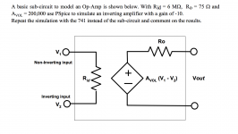
Attached is a simulation that I need to complete on LTSpice (MAC) for a report that I need to submit. I have also attached my latest attempt at the subcircuit but it is not giving the correct output according to the assignment's specs. I am new to LTSpice but eager to learn how to use it properly. Thank you!
View attachment Lab 10 sch3.pdf

View attachment Lab 10 sch3.pdf

Did you create the inverting amp with gain of -10 yet using an ideal Op Amp? Also what are the R1 and R2 resistors for?
There are two mistakes. The first mistake is that you've got the negative end of the "E" element, tied to the negative input pin. That's wrong. The negative end of the "E" element goes to ground (the label "Vout2" and resistor R2 disappear).
The second mistake is: R3 and R4 are WAY too small! You've got them smaller than the open loop output impedance of the opamp (Ro = 75 ohms) and that is disastrous. Change them to 33K and 3.3K respectively.
R1 is a "voodoo" element: it does nothing except make the human psyche believe that some kind of mysterious monster has been tamed. When you fix the two mistakes above you can delete R1 and nothing bad will happen.
By the way you want V2 to have a DC value of 0 volts and an AC value of 1 volt. Whatever that "10" is, it's not right.
- Status
- Not open for further replies.