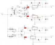
Hey guys, I hope you could help me with modding my Delta 1010's PSU. Below is a schematic that reflects the latest changes I have done. The circuit employs a voltage doubler that is used to generate +15V and -15V, and two half-wave rectifiers to generate the +5V rails. The 9VAC input is from a wall wart rated for 3.5A that converts the mains 110VAC to 9VAC. That is its rated spec but the actual input voltage I'm reading is 10.95VAC.
My problem is that I'm unable to get a clean voltage into and out of the +15V reg U4. The way I'm checking this is by measuring the AC voltage on the input and output of U4 (I don't have a scope). When I try to measure the voltage, I'm unable to get a reading because my meter fluctuates wildly. But I'm not getting this fluctuation when I measure the AC voltage on the input and output of the other regulators (they are giving me near zero AC voltage). I think this means something is wrong with either the +15V reg itself or the supply voltage going into it. Can someone please help me to sort this out? What are the things that I should check for? What other mods would you suggest to clean it up?
Any help would be greatly appreciated. Thanks in advance! 🙂
Attachments
Since no one is responding, maybe I should ask more specific questions:
1. What do you think of the value of C14 and C17 (currently 660uF). Are they too small? What value would you suggest?
2. What about the value of C12 and C18 (currently 3400uF). Are they too large? What value would you suggest?
3. Do you think it will improve the power supply if I replace all the UF4002 diodes with Schottky type MBR1100?
Someone help me, please!!! 😱
I want to experiment with changing the value of the capacitors C14 and C17. But first, I need to know what exactly is the function of these capacitors. Can someone please explain what these capacitors are doing in the circuit? Please be easy on me as I have only a little knowledge of electronics. I'm just handy with a soldering iron. 😱
Next question is the choice of the best capacitor for C14 and C17. I'm guessing that low ESR and high ripple current rating are some of the important considerations, and of course the voltage rating of the capacitor. I measured the voltage across C14 and it's only 13.6VDC. Therefore, I think that any voltage rating from 25V and up would be fine. I am currently looking at the following capacitor options:
Panasonic FM 820uF 25V, 0.018R Impedance, 2470mA Rated Ripple
- or -
Panasonic FM 560uF 35V, 0.018R Impedance, 2470mA Rated Ripple
I want to know which one of these would be the better choice. So the impedance and rated ripple of these are the same, the voltage rating is adequate for both, and the only question is the capacitance value. All things being equal, should I choose the one with the higher capacitance? Is higher capacitance a good thing and an important consideration for the function of this particular capacitor?
Thanks, and I hope someone could please kindly help me with this question! 🙂
Last edited:
- Status
- Not open for further replies.