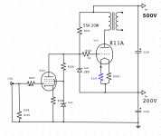
I would like to build a tube amp based on 811A with partial feedback. I got inspired by Gary Pimm's Tabor PP amp but I would like to do it in Single end.
I draw up a schematic and need opinion from experts around here if this will work. I have not design what input tube to use. Any suggestion?🙂
I draw up a schematic and need opinion from experts around here if this will work. I have not design what input tube to use. Any suggestion?🙂
Attachments
I would like to build a tube amp based on 811A with partial feedback. I got inspired by Gary Pimm's Tabor PP amp but I would like to do it in Single end.
I draw up a schematic and need opinion from experts around here if this will work. I have not design what input tube to use. Any suggestion?🙂
With any valves running the grid positive , the driver needs to be run with plenty of current and have a low impedence such as a cathode follower or stepdown transformer . I don't think that circuit will work very well , especially as the grid has a zener shunting it 🙁 811A will be tricky to get good results from , may be a better idea to look at 826 3C24 or 809 . With 3C24 I used to use cathode feedback with the output transformer's 16 ohm tap in the cathode circuit , still found bass to be flabby and one-note , depends on the speakers used I suppose
cheers
316a
Ive used the 811A in both SE and in PP
I Really Like the power and clarity I had with the PP bread-board I made...
--It was quite amazing considering its a DHT, built I believe for R.F. work....!
The sheme you've drawn I doubt would work, TBH....
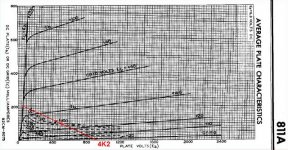
The 811A is a little bit different to the usual DHT tube, needing a Positive g1 volts to draw any current on the plate, below about 600V and it also gobbles up some considerable Current into g1 whilst doing so!...
You'll need about 22-25V positive on the G1 (I Forget the current) to make the tube draw about 60mA Plate current from a 450- 500V supply.
The 811A/572B needs a LOW Impedance drive to the grid to work at the voltages we 'normally' use in audio....
Best, (Easiest!) way I found to Drive the grid was via a MOSFET Follower from a 150-200V supply. This supply needs to be fairly stout and able to source say, 100mA if you're running 2 tubes from the same supply
--Ive seen implimentations of a big ole Pentode like a EL34 or KT66 driving the grid in C.F format but havent tried that myself, so cant comment on any issue from a Pentode C/F grid-drive
Drive the MOSFET Follower from summit like a 6SL7 strapped and you're halfway to what I built.
--The Output Tx can be anything from 2K to about 3.5K into your speaker-load, but about 2.5K load is good....
Issues I found were hum derived via the heater circuit, a hum-ballance pot in the heater supply helped but never completely eliminated the hum in my breadboard, but to be fair, the level was pretty low.
A nice DC heater could help, but at 6.3V @ 4A per 811A its a fair regulator in itself, and can make for a lot of heat!!
--Love the way they light up a dark room too!😀
I Really Like the power and clarity I had with the PP bread-board I made...
--It was quite amazing considering its a DHT, built I believe for R.F. work....!
The sheme you've drawn I doubt would work, TBH....
The 811A is a little bit different to the usual DHT tube, needing a Positive g1 volts to draw any current on the plate, below about 600V and it also gobbles up some considerable Current into g1 whilst doing so!...
You'll need about 22-25V positive on the G1 (I Forget the current) to make the tube draw about 60mA Plate current from a 450- 500V supply.
The 811A/572B needs a LOW Impedance drive to the grid to work at the voltages we 'normally' use in audio....
Best, (Easiest!) way I found to Drive the grid was via a MOSFET Follower from a 150-200V supply. This supply needs to be fairly stout and able to source say, 100mA if you're running 2 tubes from the same supply
--Ive seen implimentations of a big ole Pentode like a EL34 or KT66 driving the grid in C.F format but havent tried that myself, so cant comment on any issue from a Pentode C/F grid-drive
Drive the MOSFET Follower from summit like a 6SL7 strapped and you're halfway to what I built.
--The Output Tx can be anything from 2K to about 3.5K into your speaker-load, but about 2.5K load is good....
Issues I found were hum derived via the heater circuit, a hum-ballance pot in the heater supply helped but never completely eliminated the hum in my breadboard, but to be fair, the level was pretty low.
A nice DC heater could help, but at 6.3V @ 4A per 811A its a fair regulator in itself, and can make for a lot of heat!!
--Love the way they light up a dark room too!😀
@ Wavebourn Any suggestion on bias schematic for 811A grid?
I did not play with right-handed lamps practically. Need to think a little bit.
Why not try a triode like a ECC99 as a choke loaded cathode follower to bias the grid positive, and to adequately sink the grid current? This seems like a much more practical approach.
If you use 807 to drive 811 it will look cool!
That it would!
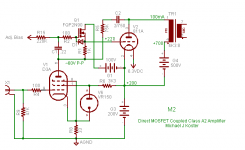
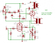
Here is how I would use the 811A in SE topology (surprised?) like a power grid tetrode but without the need for a g2 supply.
I would use a stable fixed bias supply and a MOSFET follower to drive the 811A grid (here a mu-follower/gyrator or mu-gyrator).
The feedback coupling cap is optional; you probably could drop the 475V across a feedback resistor but it will produce about 3.5W. The gyrator will fix the plate voltage and supply the needed make-up plate current.
A D3A is not needed but with a power triode you will want to keep the feedback impedance well below the Cgp reactance; Cgp is 5.6pF on the 811A. This will mean a reasonable driver gm to get good power sensitivity. Maybe an 807 would work after all. Anyway, the D3A is just an example.
This could drive the grid current in a linear way and you would get about 23 watts power out for 50W plate dissipation; pretty good for a class A SET on a balanced load line!
Hmm, if I didn't have a bunch of Eimac tubes already...
Attachments
Last edited:
Yup Micheal Koster has it!
Thats basically what I meant by the MOSFET Drive. Only change I would make is to raise the 100V 'bias' and MOSFET supply to 150V as I found that 100V was not sufficient on peaks where the drive ran out of steam...
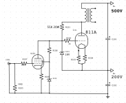
Personally, I would forget your original scheme, that 18V Zener would kill any positive signal drive anyway, clamping it to 18V!--basically, it just wont work like that. The 1K in the g1 will limit current and therefore plate current way too much, and I doubt the driver would be able to source the current needed anyway, even with a 50K plate load!
Go with the MOSFET stage exactly as Micheal above has posted, and drive it with a gain-stage of your choice....
--At least you can then get it working and play around with it, measure the Actual g1 current its consuming at various power levels, then develop a driver stage to suit if you dont like the MOSFET........
Gate volts sets the Plate current by a simple pot, and easily set up. I found that once set, the current doesn't vary hardly at all, --very little drift with time....
Thats basically what I meant by the MOSFET Drive. Only change I would make is to raise the 100V 'bias' and MOSFET supply to 150V as I found that 100V was not sufficient on peaks where the drive ran out of steam...
Personally, I would forget your original scheme, that 18V Zener would kill any positive signal drive anyway, clamping it to 18V!--basically, it just wont work like that. The 1K in the g1 will limit current and therefore plate current way too much, and I doubt the driver would be able to source the current needed anyway, even with a 50K plate load!
Go with the MOSFET stage exactly as Micheal above has posted, and drive it with a gain-stage of your choice....
--At least you can then get it working and play around with it, measure the Actual g1 current its consuming at various power levels, then develop a driver stage to suit if you dont like the MOSFET........
Gate volts sets the Plate current by a simple pot, and easily set up. I found that once set, the current doesn't vary hardly at all, --very little drift with time....
Yep. Do as Michael said, with Gyrator loaded 807 driver. Should look pretty cool!
Bolt MOSFET to the chassis, underneath, so only nice looking lamps will be visible.
Bolt MOSFET to the chassis, underneath, so only nice looking lamps will be visible.
An externally hosted image should be here but it was not working when we last tested it.
An externally hosted image should be here but it was not working when we last tested it.
Last edited:
@ Michael Koster Love your circuit. Thank you so much
Also like the look of 807 and 811A. Will have to try this out.
Time to go shopping now.🙂
Also like the look of 807 and 811A. Will have to try this out.
Time to go shopping now.🙂
Another nice feature for high mu, high impedance triodes. Filament hum appears at the plate at the same equivalent voltage as at the filament. Meaning it's probably acceptable (to be tested) to use AC to power the filaments on these big tubes. Power hum and voltage hum are both passed to the plate without amplification as the feedback cancels all but the original cathode hum signal.
I have some 35TGs I'd like to light up and this might be an easy thing to test out.
I also think it's possible with a tube drawing grid current all the time, that is with little or no discontinuity, that some simplification of the power supply could be done. Here is one meant to run from a 480V control transformer based power supply with 600V B+ and a center tap for the driver. This is what I'm thinking about building for my next reading lamp amp.
Attachments
Last edited:
It´s been years since I played with the good old 811A but here´s a few things that I learned:
* Forget AC heating. I used large iron core chokes and massive amounts of capacitance in order to get clean DC, active regulation might be another way to go.
* The dynamic grid impedance is low and very non-linear, make sure that the output impedance from the driver also is very low to avoid distortion. I used triode wired 6CW5´s (EL86) as cathode followers, worked good enough but if I´d do it again I would use mosfets. If using tubes, choose a high gm type that can pass 100mA at the positive signal peaks.
* Make sure that the plate voltage comes up before the positive grid bias, the opposite scenario may result in a nasty grid meltdown.
* 811A and similar high mu triodes behaves more or less as pentodes so you will probably need some feedback to get the output impedance down to usable levels.
* If you´re not in for the challenge, choose some other tube. Class A2 is a mess.
Another nice feature for high mu, high impedance triodes. Filament hum appears at the plate at the same equivalent voltage as at the filament. Meaning it's probably acceptable (to be tested) to use AC to power the filaments on these big tubes. Power hum and voltage hum are both passed to the plate without amplification as the feedback cancels all but the original cathode hum signal.
I have some 35TGs I'd like to light up and this might be an easy thing to test out.
I also think it's possible with a tube drawing grid current all the time, that is with little or no discontinuity, that some simplification of the power supply could be done. Here is one meant to run from a 480V control transformer based power supply with 600V B+ and a center tap for the driver. This is what I'm thinking about building for my next reading lamp amp.
I am not follow you on this circuit. It seem like the current from 600V B+ pass through output transformer - plate -cathode then Q4 before full circle. Q4 must dissipate 10 watts. Is this correct?
I am not follow you on this circuit. It seem like the current from 600V B+ pass through output transformer - plate -cathode then Q4 before full circle. Q4 must dissipate 10 watts. Is this correct?
Yes, Q4 and associated circuit is a shunt regulator. It replaces the lower power supply. It is expected to hold the cathode voltage perfect while current changes over the whole output and grid swing. This is experimental and I don't know how well it will work without further development. I just wanted to show the separate idea of using AC for the filament because the feedback will cancel most of it.
I am more confident in the circuit from the earlier post and I have more experience with the stacked supply topology.
Cheers,
Michael
- Status
- Not open for further replies.
- Home
- Amplifiers
- Tubes / Valves
- Need help on 811A partial feedback