hello friends,
i have jvc AX-A372 have many essues, i bought it fixed,
the things that was fixed in it are : removed IC502, removed D502, IC901 related between pin7 and pin8 however i don't know why in the right Chennel.
The left Channel works.
I bought IC "VC5022" to fix JVC-AX330 from AliExpress to be sure that's work, I put it in JVC-AX372, in the left channel, whenever I start it, it starts singing for 4 or 5 seconds then the output transistors Q511 and Q513 in the left channels stop working.
i tried to fix it even if i have no large experience about it, i've changed the pieces that burned which are "Q508, Q510, Q509, Q507" from AliExpress.and the resistor R520.
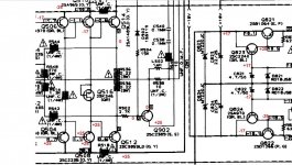
The amplifiers did'nt give me the value that i should find in the Emetters Q513 and Q511. it gives me in yhe Emetter Q513: -17V, and gives me in the Emetter Q511: +25V.
I tried to chande the pieces manually since i have them, "Q541,Q542,Q543,Q544" originals.
Then i've changed the original pieces: "Q515, Q516".
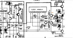
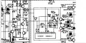
then i decided to change Q503, Q504, Q505 and Q506 from AliExpress. I find that R513 and R514 get warm, and the amplifie did'nt give me the values that I must find, Which are found in the shema (i will send it earlier), without put the original piece IC501 because it's unavailable, i keep it safe untill i fix the amplifier.
i have jvc AX-A372 have many essues, i bought it fixed,
the things that was fixed in it are : removed IC502, removed D502, IC901 related between pin7 and pin8 however i don't know why in the right Chennel.
The left Channel works.
I bought IC "VC5022" to fix JVC-AX330 from AliExpress to be sure that's work, I put it in JVC-AX372, in the left channel, whenever I start it, it starts singing for 4 or 5 seconds then the output transistors Q511 and Q513 in the left channels stop working.
i tried to fix it even if i have no large experience about it, i've changed the pieces that burned which are "Q508, Q510, Q509, Q507" from AliExpress.and the resistor R520.
The amplifiers did'nt give me the value that i should find in the Emetters Q513 and Q511. it gives me in yhe Emetter Q513: -17V, and gives me in the Emetter Q511: +25V.
I tried to chande the pieces manually since i have them, "Q541,Q542,Q543,Q544" originals.
Then i've changed the original pieces: "Q515, Q516".
then i decided to change Q503, Q504, Q505 and Q506 from AliExpress. I find that R513 and R514 get warm, and the amplifie did'nt give me the values that I must find, Which are found in the shema (i will send it earlier), without put the original piece IC501 because it's unavailable, i keep it safe untill i fix the amplifier.
Attachments
Stop buying from aliexpress. It is almost guaranteed to be counterfeit rubbish.
ebay etc are not a great deal better.
ebay etc are not a great deal better.
Transistors have already worked with them and they give a good result..As for the escissors ic's...., I have not tried them before
datasheetcatalog.com has no data on vc5022 to even know how it is supposed to work. Random garbage from ***** is not going to help anything. A church I support bought a replacement shade driver board loaded with 27 pieces of plastic that looked like transistors, had the right numbers, but were 3 legged bits of garbage. Engineer is dead, nobody left at that shop knows anything but BOM & how to assemble them. Service dept can't even detect fake transistors.
Scrap these boards and maybe reuse the power transformer, case, & controls for something else. Some apex board or something compatible with the rail voltages. Or buy some US or UK made "amp for parts or repair "you can get data on. I picked up a QSC 325 w/ch amp 2 weeks ago for $106 + tax + freight. Worked. CX302 is totally documented. Will replace a QSC amp at a church that one channel is dead, has digital controls nobody knows how to operate if that channel is just turned off. No user's manual available and microprocessors that don't work could have any problem. Last summer bought a blown PV-4c for $24 + tax & freight. Totally documented & understandable. I repaired one PV-4c I paid $24 for <$100 parts that was stolen last year.
Scrap these boards and maybe reuse the power transformer, case, & controls for something else. Some apex board or something compatible with the rail voltages. Or buy some US or UK made "amp for parts or repair "you can get data on. I picked up a QSC 325 w/ch amp 2 weeks ago for $106 + tax + freight. Worked. CX302 is totally documented. Will replace a QSC amp at a church that one channel is dead, has digital controls nobody knows how to operate if that channel is just turned off. No user's manual available and microprocessors that don't work could have any problem. Last summer bought a blown PV-4c for $24 + tax & freight. Totally documented & understandable. I repaired one PV-4c I paid $24 for <$100 parts that was stolen last year.
Last edited:
Hello friend,
A better way would be to temporarily protect the components from high current, so you can power on, make some measurements then use logic and thinking to measure and find the bad component.
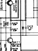
So I suggest that after you replace all defective transistors and resistors with good ones you place a diode over C419 (over C420 for the other channel) as in the attached schematic. This will limit the current going through the power transistors. Respect diode polarity, the cathode of the diode towards Q411 (respectively Q412 for the other channel). Then power up and measure the voltage in emitters Q513 , Q511 and report back here. If you measure anything else than close to 0V do not keep the power on for long (action plan: be prepared to measure, turn the power on, measure, turn the power off)
Do you mean they got destroyed ?the output transistors Q511 and Q513 in the left channels stop working.
One or both of 0.22 ohm resistors in R536 is interrupted. This also explains why R514 gets warm.it gives me in yhe Emetter Q513: -17V, and gives me in the Emetter Q511: +25V.
Here is the thing my friend: there is one component that caused the destruction of all these transistors and resistors; if you replace them but you miss (that) just one defective component you could end up burning those transistors and resistors again....I tried to change ... Then i've changed ... then i decided to change...
A better way would be to temporarily protect the components from high current, so you can power on, make some measurements then use logic and thinking to measure and find the bad component.
So I suggest that after you replace all defective transistors and resistors with good ones you place a diode over C419 (over C420 for the other channel) as in the attached schematic. This will limit the current going through the power transistors. Respect diode polarity, the cathode of the diode towards Q411 (respectively Q412 for the other channel). Then power up and measure the voltage in emitters Q513 , Q511 and report back here. If you measure anything else than close to 0V do not keep the power on for long (action plan: be prepared to measure, turn the power on, measure, turn the power off)
Attachments
Last edited:
- Home
- Amplifiers
- Solid State
- Need help - jvc ax 372