Hello.
Recently I build a sub woofer based in a selenium 12w5 speaker and INUKE 3000 DSP.
The speaker has a huge magnetic motor which implies in high inductance.
The speaker is wired for 4 Ohms. When the bridged INUKE reaches around 50 Volts peak (100 Volts peak to peak) at very low frequencies it starts to turn the speaker output off and back ON at a rate around roughly twice a second .
It causes a loud sound similar to the voice coil hitting the magnetic structure. Really not nice.
I would like to know how to avoid this to happen. So far I imagine this is a protection system triggering due to the high phase between voltage and current.
Any ideas?
Thanks
Flavio
Inuke 3000 DSP has output of about 2000 W to 4 ohm load (bridged) - that is too much for the Selenium 12w5. Use internal DSP to set up the limiter and add a 35 Hz (or so) high-pass filter.
Inuke 3000 DSP has output of about 2000 W to 4 ohm load (bridged) - that is too much for the Selenium 12w5. Use internal DSP to set up the limiter and add a 35 Hz (or so) high-pass filter.
Hello,
I did not explained completelly the construction of the sub, or added the measurements I performed before asking for help... my Fault😉
I changed the speaker spyders and suspension, in order to reduce the ressonance frequency to around 24Hz. with this I could get a 110dB SPL from 15Hz to 40Hz, measured in the seats at my living room. please see the picture attached. And the objective of this sub was to really feel the subsonic frequencies, and this goal was reached. So a High pass in 35 Hertz, which would be adequate for the original sub, it is not desired here.
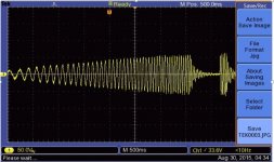
Regarding the "hitting or bottoning sound" , please see the graph of Inuke voltage versus time below. when the voltage reaches a little bit over 60Vp, the output is cutted, and the turned ON like flipping a switch after half second. the sound of the system going back ON is very LOUD. I intend to avoid that it turning ON and OFF often.
My first thought is that at 60Vp the protection circuit triggers and disconect the outputs at once, and turn it ON again after 500 mSec, as you can see in the picture below.
I understand that 60 Volts peak means around 42 VRMS, which in 4 Ohms would give 42 x 42 /4= aproximatelly 400Watts RMS, which is a lot less than the Inuke 3000 can deliver when bridged.
Finally, I do not intend to put more power in the 12W5, but avoid triggering the outputs ON/OFF.
Setting the limiter to minus 3 dB does not change the simptons.
In case I did not understood the basics , please feel free to correct.
Thanks in advance,
Flávio
Attachments
i have no explanation for the behavior you are seeing. maybe the inuke's cheap power supply cannot deliver 400w continuously, so it goes hiccup mode. remember the 2000w are for short bursts.
why not try setting the limiter at -9db to aviod that situation at all?
why not try setting the limiter at -9db to aviod that situation at all?
I am quite positive that Inuke 3000 can deliver at least 1000 W continuously at 4 ohm RESISTOR, in bridge. Complex woofer impedance with low impedance plus high phase angle at some frequencies can drain too much blood from the amplifier (triggering the amp protection), but at other bass frequencies amplifier will deliver 1000 W. Selenium 12SW5 is "only" 650 W. Setting the limiter at -3 dB is mandatory, and maybe it requires more than that.
Radically modifying the woofer with too soft spider and surround is asking for a trouble. Can you post measured impedance and phase of the 12SW5 sub?
I can't see the details from the oscilloscope sweep caption - it seems that sweep increases both amplitude and frequency with time. Which are the lowest and the highest frequencies of the sweep? Maybe it is not the amplitude as such which causes the trouble, but the amplitude at particular frequency?
Last edited:
Since inuke is class D, it should have no issue with phase at all. the only things that count are: current/temperature for the output stage and power / temperature for the PSU.
You are absolutely right about class D immunity to phase issues (in an ideal case), but we should remember we are talking about Behringer, not Crown...
I am quite positive that Inuke 3000 can deliver at least 1000 W continuously at 4 ohm RESISTOR, in bridge. Complex woofer impedance with low impedance plus high phase angle at some frequencies can drain too much blood from the amplifier (triggering the amp protection), but at other bass frequencies amplifier will deliver 1000 W. Selenium 12SW5 is "only" 650 W. Setting the limiter at -3 dB is mandatory, and maybe it requires more than that.
Radically modifying the woofer with too soft spider and surround is asking for a trouble. Can you post measured impedance and phase of the 12SW5 sub?
I can't see the details from the oscilloscope sweep caption - it seems that sweep increases both amplitude and frequency with time. Which are the lowest and the highest frequencies of the sweep? Maybe it is not the amplitude as such which causes the trouble, but the amplitude at particular frequency?
First, thanks for the ideas so far.
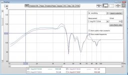
I just measured the impedance/phase using REW and a behringer DAC interface. please see the picture attached.
I have "ONLY" 60 degrees of phase .... the amplifier will be putting a lot of current when the output is at Zero Volts. Or even worst, in certain moments tha amplifier will not supply current but "absorbe " ( is this the correct english word for -consume, take?) the current produced by the woofer, and this should go to the power supply.
Am I correct in this analysis?
I can not imagine a way to correct the phase in this subwoofer. is there any whithout using massive caps and inductors?
Thanks,
Flavio
and besides i do not like the idea,it seems that I am going to use the limiter to avoid the protection system.
Attachments
Since inuke is class D, it should have no issue with phase at all. the only things that count are: current/temperature for the output stage and power / temperature for the PSU.
I do not know the background of why a Class D should not have problems with phase... I remember a paper from Bob Carver describing the high back EMF produced by his small subwoofers, and thecountermeasures he took.
just found the article. I think it is interesting:
BC: The True Subwoofer is a small box with a small driver that produces the same output and bass extension as a large box with a large driver. It has not been possible until now to build a small subwoofer with this kind of output. Conventional drivers are not very efficient at converting input power into motion. They operate close to “stall mode” where a lot of power is turned to heat. To get lots of output from a small box, we have to increase input power by a factor of 10 or more. Two hundred watts becomes 2,000 watts, and that burns out the voice coil. What was necessary was to make a driver that would remain highly efficient even in a small box. This requires a big magnet and lots of motion, which pulls the driver out of stall. When it’s out of stall, it’s efficient and there’s far less heat.
This flies in the face of conventional driver design, because that type of driver generates vast amounts of back emf [back electromotive force, which results when the motion of the voice coil in the magnet gap generates a voltage]. The back emf prevents current from flowing through the voice coil, so there isn’t any output. To overcome the back emf, you need a special amplifier that can swing 100 volts, rather than 20 or 30 volts. When you compute the input power - 100 volts squared divided by four ohms, the resistance of the speaker - that’s over 2,000 watts. That’s what the amplifier would deliver if the load were purely resistive. But it’s not. It’s a loudspeaker load with high back emf. The real power delivered to the voice coil is only a few hundred watts.
GB: Is that the explanation of the controversial power specification of the True Subwoofer? That its amplifier delivers a few hundred watts into the resistive component of the load, but that it has to be capable of delivering far more power in order to deal with the reactive component of the load.
BC: You can think of it in those terms. That’s called “imaginary power.”
bla bla bla.....
The Sunfire True Subwoofer’s cabinet is very small - 11 by 11 by 11 inches. To get lots of deep bass from a cabinet this small requires a very powerful amplifier. Sunfire rates its subwoofer amplifier at 2,700 watts!
The driver design that displaces so much air also prevents it from burning up. Conventional moving coil speakers are inefficient at turning input power into cone motion. To move the cone, they require a lot of current passing through the voice coil. This produces heat. More input power means more heat.
You can increase driver efficiency by using a more powerful magnet and longer voice-coil excursion. Normally, this is completely impractical. This combination results in high amounts of back electromotive force (emf). The motion of the voice coil in the magnet gap produces a voltage. If the amplifier cannot overcome the voltage produced by the motion of the speaker, no current can flow into the voice coil, and there is no sound.
For such a driver to work, you need an amplifier capable of very wide voltage swings. The tracking downconverter amplifier used in the Sunfire subwoofer can swing over 100 volts. Because of heating problems and space limitations, it would be impossible to use a conventional amplifier that could swing 100 volts into a four-ohm load. But because a tracking downcoverter amplifier runs cool, does not require heat sinking or a large power supply, it can be made small enough to work in this application.
With this kind of amplifier, back emf becomes an asset. The Sunfire sub’s long driver excursion and huge magnet (225 ounces) produce large amounts of back emf, which prevents damaging amounts of current from flowing into the voice coil. Consequently, the voice coil does not burn out. The huge magnet enables the long excursion even though the amount of current flowing in the voice coil is small.
Only a small portion of the output from the True Subwoofer’s unusual amplifier flows into the voice coil as current. Most of it is used to overcome the huge back emf produced by its unusual driver.
I found it at:
Audio Ideas Guide Interviews: AIG Talks with Bob Carver
Now my question would be: is it the Inuke sensible to high speaker phases, high back EMF ( I understand that high phases implies in high EMF , correct?) or is it another point?
thanks , Flavio
Hmm... 60 degrees is high indeed, but impedance at that frequencies is also pretty high, so there should be no problems - current is not that big.I have "ONLY" 60 degrees of phase .... the amplifier will be putting a lot of current when the output is at Zero Volts. Or even worst, in certain moments tha amplifier will not supply current but "absorbe " ( is this the correct english word for -consume, take?) the current produced by the woofer, and this should go to the power supply.
Am I correct in this analysis?
I can not imagine a way to correct the phase in this subwoofer. is there any whithout using massive caps and inductors?
Yes, current will dump in to the power supply - no problem for a good power supply, but for a Behringer power supply...
No sensible way to "correct" the subwoofer phase, only remedy is high quality amplifier.
Short story: class D amplifier connects woofer (briefly) directly with the power supply, which source or dump current. So power supply should be very good in quality.I do not know the background of why a Class D should not have problems with phase...
there is no need to correct any phase - Class D is class D no matter what vendor and the power is cycled back and forth between speaker and rail capacitors.
- Status
- Not open for further replies.
- Home
- Amplifiers
- Class D
- Need help: INuke protection system X subwoofer