Hello,
Looks like switches, can't tell without seeing how they are driven, but a solid state relay/switch seems likely.
Looks like switches, can't tell without seeing how they are driven, but a solid state relay/switch seems likely.
Something quite clearly went horribly wrong with these images. The server days:
You sure don't see that every day.Request-URI Too Large
The requested URL's length exceeds the capacity limit for this server.
I checked the actual chip on the amp (duh!), says "SN99661" and "70400604". Then from Google, found forum post: "This is a Peavey part number (70400604) and it is for a discontinued
TL604 (SN99661) switch used for channel/effects switching in Peavey and
some older Fender amps. Peavey sells a kit (part no 96500078) using a
small PCB with some other switches as a replacement. It should cost
about
$30-$35 and any Peavey service center can order you one. You might call
Peavey directly and give them a try."
And I realized, seeing the "F.S." (footswitch), that it is an electronic switch of some kind. I don't have the footswitch, and the amp works without it, so I'm back to just checking it out (with scope and sig-gen). Thanks!
This is the perfect example of why I like Peavey so much. Most companies try to support their products, but after a few years they let it drop. Peavey supports products as long as they can, in fact certain pots have had two part number revisions as they replaced the original type with a drop in of a later design. same footprint, same shaft/knob, different vendor. I can routinely buy parts for 20 year old models from PV.
The TL604 is an electronic switch for the signal path. TI made them, and PV used them by the thousands in MANY of their solid state products from the 1980s on.
Then TI stopped making them. Any other company would have said "Well, sorry, but they don't make those any more." Not Peavey. They designed a small board with a couple of small ICs on it that does the same function. The small board has eight long legs sticking down in the DIP-8 pattern, so you can solder it right in place of the old IC. The board sits up off the main board enough to clear any other small parts around the old IC. Seamless and simple.
They made that effort so you and I can continue to use PV amplifiers from 25 years ago. So much for the people who post abut companies not wanting people to be able to repair things.
It would not be difficult to knock together a substitute circuit of your own, but why bother?
The TL604 is a dual channel switch. The control input switches one channel on and the other off. So they can use one channel of it as an on/off - like turning the reverb on and off. They can connect the two outputs together, and it becomes an A/B switch, like channel selecting or something. That explains the two images in your DOC file. The upper one is an on/off, while the lower one is a selector.
In two channel PV amps with automix or channel selection, those 604s are used as channel kills. To use channel A, they turn off channel B. When not using the automix jack, both channels stay on, so if you have no footswitch to kill either channel, then the 604 switching won't matter. As you apparently found out.
If you need to get the amp working and don't want to or don't have the time to get the replacement thingie, one trick is to steal one. If channel switching IC is broken, but the reverb works, I steal the reverb one and install it where it needs to be for channels. I then put a jumper wire in the reverb 604 socket, so the reverb is always on. Turn the reverb off by zeroing its control. In the upper drawing in your DOC, a jumper from pin 7 to pin 3 or 4 leaves it on.
Abacus Technologies has 1,050 new-old-stock TL064s (made by Texas Instruments) on the shelf and ready to ship. They are one of those call-for-a-quote places. Call them and get a quote.
Rochester Electronics has 1,567 TL064s in stock.
Quest Components has 214 Texas Instruments "TL064CPS" in stock for $2.14. Do I know what "CPS" means? No I do not.
BTW I found all of these and more with a single web search.
Rochester Electronics has 1,567 TL064s in stock.
Quest Components has 214 Texas Instruments "TL064CPS" in stock for $2.14. Do I know what "CPS" means? No I do not.
BTW I found all of these and more with a single web search.
Thanks Enzo! Your experience and contributions to this forum are priceless... I'm not sure how that Automix works, only have the schematic not the manual (or footswitch), but just poking around the amp is keeping me busy. Solid state seems more complicated than tube circuits, but as I learn more it makes more sense. Is there a "chip" wizard out there (like the awesome Valve Wizard), or other amp related SS resources on the web? Thanks again!
P.S. the power tube section is basic: - 57V bias supply, 475V on plate, 473 on screen, grounded cathode. Now the PI....looks like an LTP. But what are all those diodes for....? Will leave that for later...
P.S. the power tube section is basic: - 57V bias supply, 475V on plate, 473 on screen, grounded cathode. Now the PI....looks like an LTP. But what are all those diodes for....? Will leave that for later...
Which model is it? Automix is not hard to understand, but we'd want the whole schematic to refer to. I don't feel like wading through all my PV hybrids to see which one you lifted those drawings from. I would assume it might be the Classic you discussed elsewhere, but you tell me. Then we will talk diodes.
@Mark Johnson. careful, we are talking about the dual analog switch IC TL604, not the TL064 quad op amp. Very different parts.
The letters after the type number refer to revision levels and also packaging usually. I don't offhand know what the PS means. The data sheet for the series is 53 pages long.
Mouser has a lot of them too. But we need the TL604 instead.
GEEK, several of us from elsewhere come here too. SSGuitar.com is a small forum about solid state guitar amps. Music-electronics-forum.com is interested in guitar amps and related stuff in general. A lot of tubies over there, but a lot of solid state talk too. Myself, Fahey, Loudthud post over there, along with a lot of other knowledgeable folk.
Merlin has that terrific tube web site, but I myself am not aware of a SS equivalent, but then I don't need those services much. And moreso now that I have retired. There may be some terrific SS web sites.
And I cannot leave without mentioning teemuk's book. Over at SSGuitar, in the first section - AMplifier discussion - in the stickies at the top, about the fifth one down (at least as my page shows it) is titled "Book about solid stage guitar amps". It is free to download there, we didn't steal it. I highly recommend it.
Enzo, attached is the Automix diagram. I see how the footswitch will select any reverb or phaser you have dialed in, and you need to be plugged in to the Automix input and have both Normal and Bright levels set...? I will post the amp schematic when I can reduce its size, but it's the "Classic 78".
Attachments
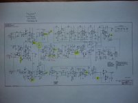
Here is the best image I could upload of the schematic. I see diodes: 1)in pairs going to + and - rails (to anchor the signal to zeroV?); 2)opposing pairs on opamp (clipping?); 3)in power amp section, from 6L6 plate-to-OT-primary-winding, going to ground (for protection?); 4) and 4 in the phase inverter - no idea. I DID download the 31MB book from Teemuk, looks incredible. Thanks for the tip!
Attachments
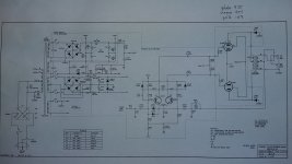
Footswitch: Remember, the channels are kills, not enables. So you have stomp switches for combine and selector. When combine switch is closed, Then the selector alternately completes the circuit to one channel or the other. That kills the one channel, leaving the other on. take your pick. Opening the combine switch means NEITHER kill has a path to ground, so both channels stay on, thus they are combined.
Diodes:
On the left, each channel input has a pair to the 15v rails, likewise lower right, the loop jacks each have a similar pair. Note they are reverse biased. They are clamps. They do nothing until the voltage exceeds the 15v rails, THEN they conduct. They prevent signal voltage from going over either 15v rail. If an IC is powered by +15 and the signal peaks to +20, as far as the IC is concerned, it sees a 5v reverse polarity.
The ones on the OT primary are flyback diodes, and they limit how large a voltage spike can come from the transformer winding. It is there to protect the OT against someone playing the amp without a load.
The ones in the phase inverter are there as protection as well, limiting certain unwanted things from happening.
Hi Enzo, Like many who have come across the now obsolete TL604 I have found a similar device from Analogue Devices in the ADC419. Switch logic is inverted in comparison to the TL604 but basically the same device. Can provide PCB layout or vero board layout if anyone is interested?
Please do 🙂Hi Enzo, Like many who have come across the now obsolete TL604 I have found a similar device from Analogue Devices in the ADC419. Switch logic is inverted in comparison to the TL604 but basically the same device. Can provide PCB layout or vero board layout if anyone is interested?
Not everyday but now and then an amp using them needs repair and it's really hard to find.
Worst case , even if it works "the other way" it's still useful; after all, if used to switch clean/dirty our ears "should" notice which is which 😱 without looking at a panel Led, and still push-push switches to "the other sound" and back again, so no big deal 🙂
TL604 to ADG419 mod
I have attached a pdf detailing a mod that I use to overcome the obsolete TL604.
I use a (readily available) ADC419 analogue switch which is functionally the same as the TL604 and invert the switch inputs as the logic is reversed, a 10k resistor and a 5.1v zener connected in series provide 5v logic supply to pin 5 of the ADC419 from the node/junction of resistor and zener.
Cheers,
Donian
Attachments
Last edited:
- Status
- Not open for further replies.
- Home
- Live Sound
- Instruments and Amps
- Need help ID'ing OP Amp schematic symbols