hi,
i need help in identifying these components. some of them are found in the feedback loop of the op-amp in parallel with the resistor. i figured they might be capacitors. if they are, i can't seem to find any info about them
here are the photos.
is it possible to make out the values of whatever these components are by looking at the labels?
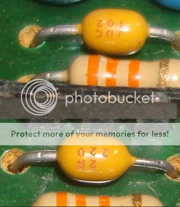
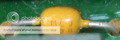
they are marked 2A 220, JDC 102, SE 103.
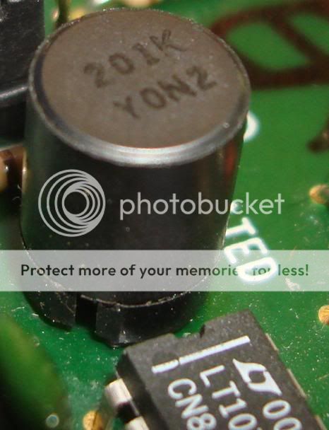
and would also like to know what this is. there is a LT1072 beside it and an electrolytic cap before going into a zener-transfomer track
thanks.
i need help in identifying these components. some of them are found in the feedback loop of the op-amp in parallel with the resistor. i figured they might be capacitors. if they are, i can't seem to find any info about them
here are the photos.
is it possible to make out the values of whatever these components are by looking at the labels?
they are marked 2A 220, JDC 102, SE 103.
and would also like to know what this is. there is a LT1072 beside it and an electrolytic cap before going into a zener-transfomer track
thanks.
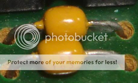
Yellow blobs are capacitors.
Biege component with 3 orange bands is a 33k resistor.
LT1072 is a switch mode regulator.
Biege component with 3 orange bands is a 33k resistor.
LT1072 is a switch mode regulator.
thanks nigel,
how do i know the values of the yellow caps? i tried removing one of them and my meter could only read down to .003nF and it doesn't register the value?😕 could be in the pF range?
also, the last photo, i'm refering to the black component with 201k Y0N2 labeled. could this also be a cap? and what value is it? can't seem to find it on the google.
I'd say with 95 percent certainty that that's an inductor. The LT1072 uses an external inductor for its operation. Go to Linear Technology's website for the datasheet, that should give you some idea for the range of the inductance, as well as helping trace the circuitry. The circuit almost certainly uses a "standard" circuit shown in the datasheet.also, the last photo, i'm refering to the black component with 201k Y0N2 labeled. could this also be a cap? and what value is it? can't seem to find it on the google.
http://www.linear.com/product/LT1072
Last edited:
I'd say with 95 percent certainty that that's an inductor. The LT1072 uses an external inductor for its operation. Go to Linear Technology's website for the datasheet, that should give you some idea for the range of the inductance, as well as helping trace the circuitry. The circuit almost certainly uses a "standard" circuit shown in the datasheet.
LT1072 - 1.25A High Efficiency Switching Regulator - Linear Technology
thanks. i'll go run through the lt's data sheet again.
Hi
@ Bzhei .This may be usefull for you
spot on madtecchy! just what i needed.😀 just printed it. thanks a lot!
by the way,
what is the composition of the yellow caps?
can i replace them with Wima metallized polyprops? they're used in my old equipment that i want to freshen up. and there are just a few of them in the board.
what is the composition of the yellow caps?
can i replace them with Wima metallized polyprops? they're used in my old equipment that i want to freshen up. and there are just a few of them in the board.
They look to me like axial ceramic multi layer composition. depending what they are doing in the circuit changing to metalised polyprops may do more harm than good.
Regards Ian
Regards Ian
Last edited:
220 = 22pF and would have been a reasonable NP0 or COG dielectric.
102= 1nF and 103 =10nF would have been X7R and not much good if the value actually matters.
I am not sure what the "028" is
The ferrite part is a 200uH shielded inductor, it looks like a good quality part
102= 1nF and 103 =10nF would have been X7R and not much good if the value actually matters.
I am not sure what the "028" is
The ferrite part is a 200uH shielded inductor, it looks like a good quality part
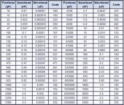
You read the numbers on the caps in picofarads as if you were reading a color code on a resistor. So 221 would be like red-red-brown, and would mean 220pf. 103 would mean the same as brown-black-orange, so 1-0-000pf, same as 0.01uf or 10nf.
They look to me like axial ceramic multi layer composition. depending what they are doing in the circuit changing to metalised polyprops may do more harm than good.
Regards Ian
i checked the circuit, the 220 caps are paralleled with a 33kohm resistor and used between the op-amps + input to RCA ground lead. the 103 caps are also paralleled with a 33kohm resistor but this time in a feedback loop from op amp output to inverting input. a 104 is used between +12 supply to gnd of the equipment itself.
220 = 22pF and would have been a reasonable NP0 or COG dielectric.
102= 1nF and 103 =10nF would have been X7R and not much good if the value actually matters.
I am not sure what the "028" is
The ferrite part is a 200uH shielded inductor, it looks like a good quality part
i just removed the cap with 028 marking. it actually read SE 103 on the other side. the 028 must have been a manufacturer code. thanks
The inductor is 220uH, not 220mH. A 220mH ferrite choke would be enormous.
Actually values of the order of 100uH are typical for these low power switching power supply chips
Actually values of the order of 100uH are typical for these low power switching power supply chips
- Status
- Not open for further replies.
- Home
- Design & Build
- Parts
- need help identifying components