I need to design a headphone amplifier with TPA6120 chip, because I don't have much knowledge about amplifier design & construction.
I'm trying to do the design as compact as possible with full SMD components. So I'm thinking of to make power supply as a seperate(wall mount adapter) or integrated(with transformers & LDO's, which will be big in size).
Now I have a doubt in my mind about the power consumption of the chip. As you can see in the attachment, the power consumption of the chip internal circuitary is very less. But the output current is 700mA which is very high. The output is not a DC voltage, so i assume that the mentioned current is a peak current. Please clarify this.
How much (RMS)current I can consider to design a power supply for the TPA6120 headphone amplifier chip?
Attachments
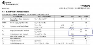
The datasheet's figure of 700mA is a typical maximum current. Unless your headphones are extremely low impedance you won't need anything near this amount of current.
The current needed from your power supply will depend on how loud you like to listen and the efficiency and impedance of your headphones. Plus the small quiescent current of the TPA.
The current needed from your power supply will depend on how loud you like to listen and the efficiency and impedance of your headphones. Plus the small quiescent current of the TPA.
I've my Audio Technica M50X which has 38 ohms impedance with 1600mW power handling capacity. If my power supply is +/- 10V. How much current I need for this condition?
ATH-M50X doesn't required an amplifier to drive, but still this is the lowest impedance headphone possibly I can use with the amplifier? Volume 😀 no idea with amplifier.
ATH-M50X doesn't required an amplifier to drive, but still this is the lowest impedance headphone possibly I can use with the amplifier? Volume 😀 no idea with amplifier.
I make it your peak current needs are 200mA to fully exercise your AT phones. Mind you that might well be an ear-splitting SPL, depending on how efficient they are.
I did a quick search for their efficiency - it says '99dB' but doesn't say whether that's a power or voltage sensitivity. Assuming its power (for 1mW) then you'll want to keep below 120dB SPL to avoid damaging your hearing, so you'll not need 1.6W peak, rather something like 120mW peak. This lower value gives a peak current of about 60mA.
I did a quick search for their efficiency - it says '99dB' but doesn't say whether that's a power or voltage sensitivity. Assuming its power (for 1mW) then you'll want to keep below 120dB SPL to avoid damaging your hearing, so you'll not need 1.6W peak, rather something like 120mW peak. This lower value gives a peak current of about 60mA.
Last edited:
Its rather short on details - for example what's going to feed the input? Is there a volume control anywhere? Is the wallwart regulated or unregulated?
The power adapter may be the same or equivalent to this.
EPSA120200U-P5P-SZ CUI Inc. | Power Supplies - External/Internal (Off-Board) | DigiKey
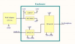
This particular power supply is regulated, but I hope this circuit doesn't required a regulated power input, its because the input power feeded to the LM317 for +10V regulated output & MC34063 will provide regulated -10v output. Now I need to know the current rating of both the power supply to design.
The volume control will be MAX5457 digital volume controller.
Udhay
EPSA120200U-P5P-SZ CUI Inc. | Power Supplies - External/Internal (Off-Board) | DigiKey
This particular power supply is regulated, but I hope this circuit doesn't required a regulated power input, its because the input power feeded to the LM317 for +10V regulated output & MC34063 will provide regulated -10v output. Now I need to know the current rating of both the power supply to design.
The volume control will be MAX5457 digital volume controller.
Udhay
That wallwart is a switcher so you'd be well advised to have additional filtering prior to any linear regulator ICs. Either a cap multiplier with discrete transistor or some series inductors.
The drop out voltage of LM317 is going to be between 1.5V and 2V depending on loading so its a bit marginal to have 12V in and 10V out - there's a tolerance on the 12V output of switching supplies, normally 5%. So your LM317 might not be in regulation at all if the switcher's output voltage is on the low side.
I'll have a look at the MAX5457 - does it go prior to the input opamp (2134) or after it?
abraxalito,
Thanks for you feedback🙂. We may have some noise from the adapter SMPS circuit. I can place a 1000µF capacitor in front of LDO & 220µF after the LDO. Do you recommend any thing alternative to this?
If I'm using a transformer power supply (with 15V DC output), will it solve the problem. Anything I can use for reduce the dimention.
Are you suggest to go with center tap transformer for dual DC power supply for better performance?
The digital volume controller I will place in front of the OPAMP.
For OPAMP amplifier which one I can select, inverting or Non-Inverting?
Udhay
Yes I have already recommended an alternative - in my experience with amps, just adding shunt caps won't cut it, you need some series inductance.
An unregulated, linear supply is probably best if you're intent on using 10V supplies (it will give you more headroom) but again series inductance does help. Since your negative reg is also a switcher its output will also benefit from HF filtering, again using inductor(s).
I've not studied the MAX chip in depth yet for your other questions.
- Status
- Not open for further replies.
- Home
- Amplifiers
- Headphone Systems
- Need help for TPA6120 Headphone Amplifier