I bought this tuner knowing that it has external power supply from XD-Z55T hifi.
Now I need to make that supply by reading components from XD-Z55T schematics that I have.
The power supply for tuner are: DC 5,6V 12v -31v and two pins marked as AC.
Everything is ok for DC but I don't know volts for that AC. I'm posting the part from schematic where you can see sub trans from which -31v dc and those two AC volts coming from.
Other interesting thing in schematic are components D101, C107 and R102 connected between -31Vdc and one AC out. And there are markings that says -20v. How is that possible?
Attachments
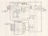
To be more precise, you do not have two AC voltages" but one winding, with one AC voltage value between them.The power supply for tuner are: DC 5,6V 12v -31v and two pins marked as AC.
Everything is ok for DC but I don't know volts for that AC. I'm posting the part from schematic where you can see sub trans from which -31v dc and those two AC volts coming from.
Which I don't know, but unless somebody has its value, you'll have to follow those 2 wires inside the tuner itself and see where they go, then an educated guess might be made.
Obviously that AC voltage must be "floating" at some DC level, reasons unknown unless we see what they do inside the tuner [2]Other interesting thing in schematic are components D101, C107 and R102 connected between -31Vdc and one AC out. And there are markings that says -20v. How is that possible?
") .
.That must be an 11V Zener, referred to ground through R102 .
It "steals" -11V from -31V and you end up with -20V .
What for?
Well, we need to know what's inside the tuner [3]
That looks like a typical supply for a VFD (vacuum fluorescent display tube) The AC voltage between the two FLACTX will only be around 3 or 4 volts AC at a guess.
The filaments are biased as JMFahey says to a negative DC voltage to enable the display to light. If you look at any CD player circuit etc you will see a similar arrangement and all the voltages will be similar too.
The filaments are biased as JMFahey says to a negative DC voltage to enable the display to light. If you look at any CD player circuit etc you will see a similar arrangement and all the voltages will be similar too.
This might help explain it all,
http://www.diyaudio.com/forums/digital-source/147694-marantz-cd5000-display-very-dull-help.html
http://www.diyaudio.com/forums/digital-source/147694-marantz-cd5000-display-very-dull-help.html

It's working! Thaks guys!
I have made one +12 and +5,6V supply, one -31v and one AC suppy with 5 volts as from schematics for Marantz you have posted for comparison.
+12 and +5 are for sound. It works without AC and -31v but without them there is no display and I can not change station
Then, I tried to connect 9v for AC and displayed was fine but red vertical lines were brighter so i got it back to 5v AC.
The thing I have noticed that there is a low hum with sound. It is gone when I plug out 5v AC. But without AC display is not working. Could it be faulty transformer? This one is the old one that I have found in the attic.
+12, +5,6v and -31 are from new transformer.
Good to hear you have sussed it out and got it working. The hum I've no quick answer for I'm afraid. You need to look at ripple content on the rails and also how you have connected any common grounds between the supplies and also how they connect to the tuner. I doubt there is an issue with the transformer.
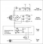
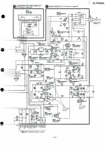
I have found a new transformer for 5V AC and new schematic to get -31V, from Technics SL-PG580A. With that in mind, I had the idea how to make a power supply for the Pioneer tuner and the active crossover thet goes in the same box with tuner.
Maybe I did not metion it but this tuner is going to be in my new boombox, including radio transmited mp3 player. I have these things laying around so I want to put them in one universal boombox
Here is the schematics.
There are two transformers, one with 5V AC and one with two 15V AC windings.
My question is: Is this going to work? In Technics SL-PG580A same 12V windings goes for -31V for display and 2x12V DC for premaplifiers.
Attachments
- Status
- This old topic is closed. If you want to reopen this topic, contact a moderator using the "Report Post" button.
- Home
- Amplifiers
- Power Supplies
- Need help for pioneer tuner power supply