Anyway, I increased the load resistor of 6G6G and the feedback resistor to have a little more gain...
Problem is, you need a LOT more gain. This circuit really needs to be rethought from the ground up.
No, not significantly. The cap can only do bad things there, if it does anything.
I don't think a cap of 100uF in parallel to 7-10 ohm (internal resistance of the two diodes) can do any bad thing, maybe it can do nothing.
What about all other caps in parallel to "much bigger" cathode resistors for self biasing? Do they do terrible disasters? 😀
Last edited:
No, not significantly. The cap can only do bad things there, if it does anything.
You get rid of about 10ohm but i agree with you that the setbacks are not worth it.
Pilovis find a high gain pentode and use plate to grid feedback.
That way you get descent power with nice distorsion figures.
You should believe SY when it comes to LED biasing. Maybe read some of his articles on the subject. If you use LEDs, you don't need a cap.
Gain is your main issue here, anyway.
Gain is your main issue here, anyway.
You should believe SY when it comes to LED biasing. Maybe read some of his articles on the subject. If you use LEDs, you don't need a cap.
Gain is your main issue here, anyway.
You're right but I don't need very much power from this amplifier, 3 W output on 8 ohm load is enough for me.
I will use it with a separate preamplifier, this is just the final stage.
Also, I choosed the 6G6G as a driver mainly for its cost (very cheap, NOS = 2 euro each here in Italy) and its low heater's current (0.15A). 😉
Last edited:
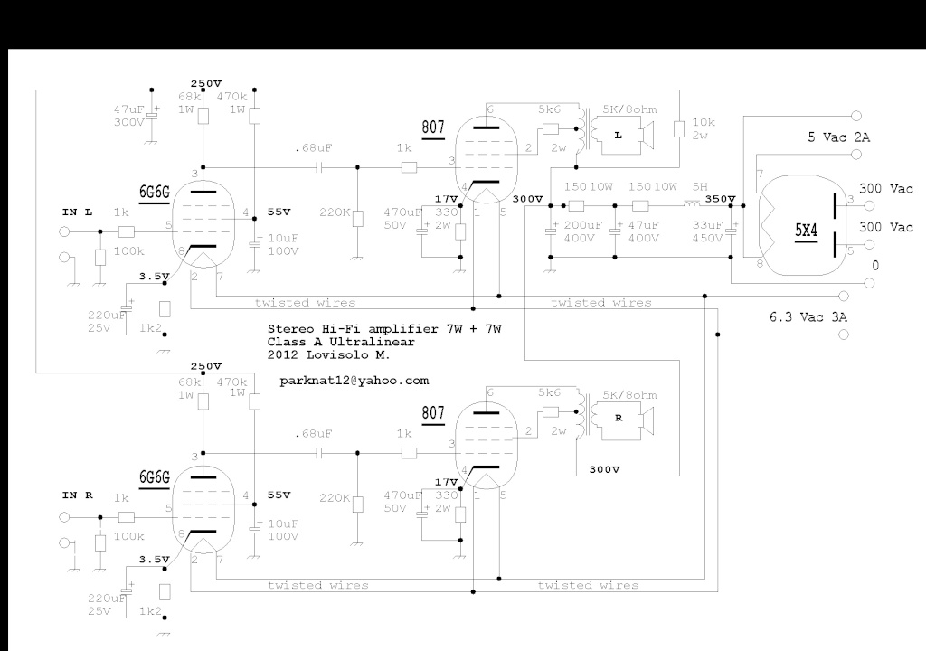
The bias circuit won't work. You only get about 9V max depending on the R & C values.
In order go get it to generate the level you seek, you would need to tie the positive rectifier output to ground instead of the CT to gnd. With the CT to gnd, you only really are using one half the transformer in a half wave rectification topology. The other half does nothing.
If you tie the +rectifier output to ground, you may risk greater hum from the heaters.
You'll have to have some major preamplification, your gain is only 0.15 or so.
A cathode resistor in a self biased circuit is a different situation than LEDs; because of impedance (and how that affects gain and output impedance), it usually requires a capacitor bypass. LEDs are much lower impedance and operate essentially as voltage sources.
Seriously, you have some fundamental problems in the circuit and you're only picking at the edges.
edit: my bad, the gain is better than that but still much too low
Wow! Mu of 9.5 when triode strapped.
Add another gain stage if you really want to use that tube.
Add another gain stage if you really want to use that tube.
Problem is, you need a LOT more gain. This circuit really needs to be rethought from the ground up.
How about a 6SJ7 in place of the 6g6g?
6CB6 strikes me as a better choice- you want transconductance, I would think, allowing you to increase the closed loop gain while keeping the source impedance to the transformer low.


So, add another gain stage?
There is no need to add any extra gain stage, the gain is more than enough, tested! 🙂.
Last edited:
Hi pilovis.
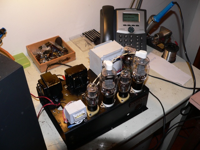
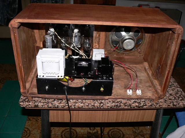
Beautiful assembly and great case. I have a couple of concerns though. I assume that the larger white transformer is the main line-power transformer, and the two black transformers are output transformers. If you connect large loudspeakers with good bass response, and you might hear more 50Hz hum in one channel than in the other that could be because the middle output transformer is mounted parallel to the line transformer. If you turn that transformer around 90 Degrees you will probably find that the hum is reduced.
A second comment is that I believe that the rectifier tube is too close to the power output tube 807. During operation the two tubes would heat each other up and may overheat the glass where they almost touch. Power-tubes like these should not be closer to each other than about 20mm.
Congratulations on a beautiful construction.
Hans J Weedon.
Last edited:
Hi pilovis.
Beautiful assembly and great case. I have a couple of concerns though. I assume that the larger white transformer is the main line-power transformer, and the two black transformers are output transformers. If you connect large loudspeakers with good bass response, and you might hear more 50Hz hum in one channel than in the other that could be because the middle output transformer is mounted parallel to the line transformer. If you turn that transformer around 90 Degrees you will probably find that the hum is reduced.
A second comment is that I believe that the rectifier tube is too close to the power output tube 807. During operation the two tubes would heat each other up and may overheat the glass where they almost touch. Power-tubes like these should not be closer to each other than about 20mm.
Congratulations on a beautiful construction.
Hans J Weedon.
Very good points!

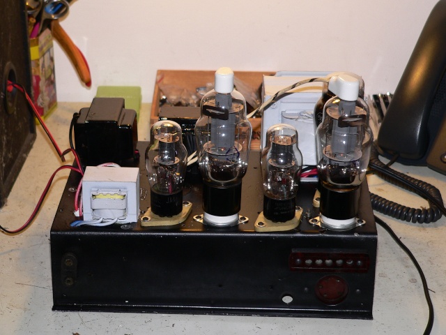
I will add a small internal fan.
Fortunately, there is no udible hum.
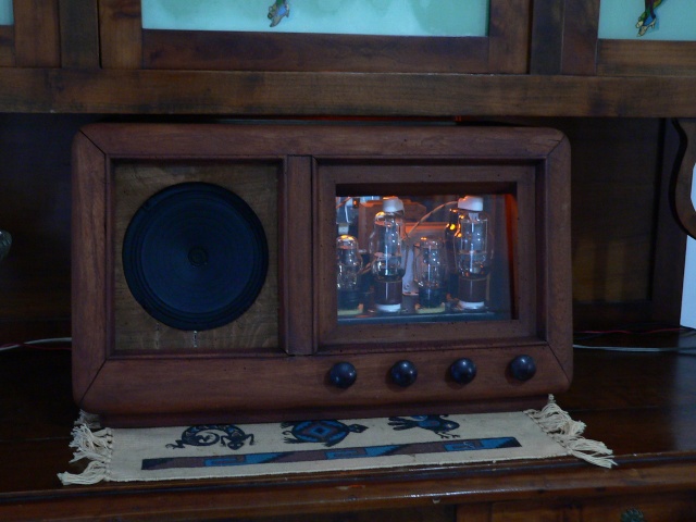
This is the video I took with my small digital camera 😱:
807 tube Ultralinear Class A - Stereo Hi-Fi Amplifier - YouTube
and just another picture:
Last edited:
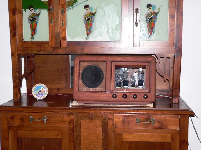
I listened to this amplifier connected to a pair of huge Warfedale E90, 100 kilograms of speakers 😀
Wow, It was amazing, at almost full volume (7+7W), the room was full of sound with no audible distortion and very good quality of sound!
Someone told me this amplifier wouldn't have enough gain, some other told me the penthode driver wouldn't have a good sound 🙄.
No comments 😀
Warfedale E90
_wharfedale_e90.jpg)
Wow, It was amazing, at almost full volume (7+7W), the room was full of sound with no audible distortion and very good quality of sound!
Someone told me this amplifier wouldn't have enough gain, some other told me the penthode driver wouldn't have a good sound 🙄.
No comments 😀
Warfedale E90
Is it possible to use this 807 tube with 3.5K output transformer? Based on the research it looks like the 3.5K a bit to low for this tube. It is a cheaper tube than the KT88, my original plan was to build a KT88 SE with the mentioned 3.5K outputs. I already have all the transformers but not the tubes. My transformer only 10W so can not parallel the tubes to better match the 3.5K.
Thanks.
Thanks.
- Home
- Amplifiers
- Tubes / Valves
- need help for my new amp: 6G6G driver & 807 SE