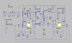
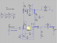
I have tried multiple values for resistors and filtering capacitor, but I don't get correct offset at the output, and filtering is not giving me needed results. Attached are LTspice schematics and LM3886 model.
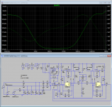
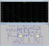
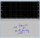
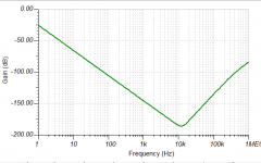
Two screenshots are showing correct and incorrect frequency responses for the servo filter.
Two screenshots are showing correct and incorrect frequency responses for the servo filter.
Attachments

Last edited:
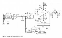
Bob Cordell's power amp textbook discusses his "Super Gainclone" design, which includes an LM3886 with a DC servo. That might be a good source of inspiration for your project.
Both the schematic, and Bob's circuit design discussion, are in the book. The schematic was also posted on diyAudio a few years ago, without Bob's comments of course.
Both the schematic, and Bob's circuit design discussion, are in the book. The schematic was also posted on diyAudio a few years ago, without Bob's comments of course.

By the way, I have started a thread on it recently - https://www.diyaudio.com/community/...m3886-trying-to-simplify.387056/#post-7044071
What node are you looking at for the frequency responses? I can see it is called n005 n007 or n003 in the plots, but where is that?
I don't understand why the DC voltage at the negative LM3886 input is always a bit higher than 1/11 of the DC voltage at the output. Is there DC coming out of V1? The LM3886 has an NPN input stage with 200 nA typical, 1 uA maximum base current, so the negative input DC voltage should be just below 1/11 times the output DC voltage.
The attenuator after U2 attenuates so much that the small DC voltage at the LM3886 input translates into a DC voltage at the op-amp output that's big enough to drive it into clipping.
correct-freq-filter.png shows it's not doing anything; gain of -90 dB or less. Why do you regard that as correct?
What node are you looking at for the frequency responses? I can see it is called n005 n007 or n003 in the plots, but where is that?
I am probing the output of the servo opamp U2, LT1056A, right before the 200k resistor.
I don't understand why the DC voltage at the negative LM3886 input is always a bit higher than 1/11 of the DC voltage at the output. Is there DC coming out of V1?
V1 should only generate 1KHz AC since wave. Not sure of that either. Maybe because of the DC voltage at the output of LM3886 that comes thru feedback resistor? Idk honestly... Maybe someone can shed the light on this one?
correct-freq-filter.png shows it's not doing anything; gain of -90 dB or less. Why do you regard that as correct?
As far as I understand, the idea is to remove any audible frequencies from the integrator circuit and only let the DC voltage to come thru.
If there is an offset voltage at the output of, say, 10mV, integrator will apply -10mV to the non-inverting input. Do I understand this correct?
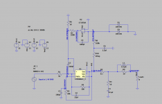
Here is the variant that follows recommendations from the TI application note, pg. 22 - https://www.ti.com/lit/an/snaa021b/snaa021b.pdf
Resistor values are adjusted accordingly. Rin = R6 = 1K. R7 = 10 * Rfb = 100K
Offset voltage at the output is 1.5V...
Resistor values are adjusted accordingly. Rin = R6 = 1K. R7 = 10 * Rfb = 100K
Offset voltage at the output is 1.5V...
Attachments
As far as I understand, the idea is to remove any audible frequencies from the integrator circuit and only let the DC voltage to come thru.
That's a bit oversimplified. The DC feedback loop can't see the difference between DC and a 1 nHz cosine, so it also responds to deep subsonic signals. Above a certain corner frequency, it starts responding less and less to the signal, but with a first-order loop, the slope is only -20 dB/decade. You can't make the corner frequency too low, otherwise settling at power up takes quite long.
All in all, I would expect a gain of about 45 dB to the op-amp output (due to the attenuator) up to the corner frequency and then a downwards slope of -20 dB/decade.
With your dimensioning, the corner frequency is roughly 0.005 Hz (0.002 Hz for the TINA version) and the settling time a few minutes. The TINA version has -40 dB/decade roll-off thanks to the extra filter.
The response from the input to the amplifier output is a high-pass with the same corner frequency.
The corner frequency is determined by the entire loop, it is in fact the point where the loop gain's magnitude is 1. The RC time of the integrator is in the equation, but also the attenuator (makes it 201 times lower) and the gain from the + input of the LM3886 to the output (makes it 11 times larger).
When you replace 10 mV at the output with 10 mV at the input, it becomes correct.If there is an offset voltage at the output of, say, 10mV, integrator will apply -10mV to the non-inverting input. Do I understand this correct?
Last edited:
A couple of quick estimates for perspective:
Referring to post 12 values, the R8/R9 divider attenuates the "Servo_Freq" voltage by a factor of ~ 1/200. So, assuming +/- 10V range at the Servo_Freq pin, the servo could cancel about +/- 50mV DC input at VG1.
Gain from Servo_Freq to the R38 load is ~ 0.055, so the time constants established by C4, C3, R5, R7 will slowed by the same factor.
For easiest insights, I suggest simulating with a 10mV step input at VG1 and observing time domain response at load output. Set C3 to 0 and vary C4 for easiest handle on behavior. You should observe a step output decaying to 0V--- i.e. a high-pass response. The residual output will be established by voltage offset at U1 and any bias current errors flowing through R5+R7. (I'd delete D1& D2--- not needed for protection.)
Cheers,
Steve
- Home
- Amplifiers
- Chip Amps
- Need help figuring out servo for LM3886 with gain of 10 in LTspice