
Nice!
It starts in ON, right?
I wonder how to make it start in OFF?
Earlier I tried Power-On Reset (POR) circuits attached, bit with no luck
It starts in ON, right?
I wonder how to make it start in OFF?
Earlier I tried Power-On Reset (POR) circuits attached, bit with no luck
Attachments
Last edited:
How about ICM7555?Using one PNP and all NPN seems like a great idea to save on idle current!
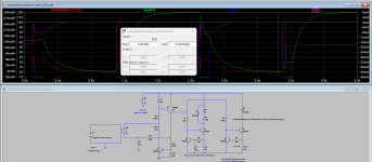
I was able to finally figure out simulation for NE555 based solution.
Consumes 4mA while idle
and 4mA+relay current (15mA)+LED current while in operation
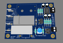
Boards are in for the transistor-based version!
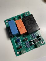
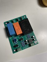
After soldering everything and powering on, it works! Tested for max LED current (20mA) and relay holding current (15mA) for 1 hour - all transistors are cold to the touch!
There is an issue, though. Upon plugging in the power cord into the outlet, the initial state of the switch is ON. I wonder if I should adjust one of the resistors to make the flip-flop start in a specific position?
And minor thing - the SMPS is making a whining sound in both the power-on and power-off states of the switch. I am assuming it is normal SMPS operation, but it’s kind of annoying when it is not 100% silent.
Attachments
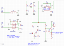
Relay is NO type.
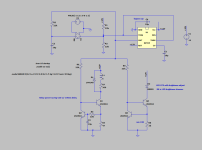
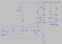
Attached is the schematics where Q1 and Q2 are the flip flop transistors.
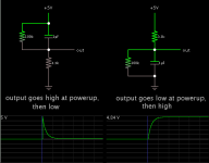
Looks like Q1 is open upon the startup. But I need Q2 to be open.
Note resistor R3 that was supposed to pull down base of Q2 to make sure it is closed upon the startup.
I suspect R4 is way higher compared to the total resistance of the other branch loaded with the relay and LED.
I might try reducing it to 22K
Attached is the schematics where Q1 and Q2 are the flip flop transistors.
Looks like Q1 is open upon the startup. But I need Q2 to be open.
Note resistor R3 that was supposed to pull down base of Q2 to make sure it is closed upon the startup.
I suspect R4 is way higher compared to the total resistance of the other branch loaded with the relay and LED.
I might try reducing it to 22K
Attachments
Last edited:
Hmmm... I always buy a NO / NC relay.
You could potentially use a pushbutton switch with NO / NC sets of contacts.. (like an E-STOP mushroom switch).. that could also help.
After contributing/reading this thread, I have decided from now on to do point-to-point wiring of the circuit I posted in #13. Very simple; it provides a predictable degree of operational repeatability, which is what you need in this instance.
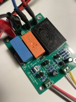
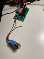
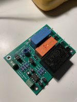
Assembled 555 based board.
Everything works great. Upon plugging in the power cord, the board stays in OFF. Pushing button turns it off/on.
Upon further testing I found that if the board is in ON and I push the button for more than one second it first turns it off but then cycles to on.
MeanWell PSU is making whining sounds either in on or off. I might just go with small linear psu. There is nice compact transformer from triad - FS12-090-C2
Attachments
- Home
- Amplifiers
- Power Supplies
- Need help designing push button mains switch based on NE555, Meanwell SMPS, and relay