HI!!! BELL2040
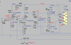
Help me calculate the diagram! I only have 260 volts! after rectification how to change the values of the resistors?
how many volts is the red arrow? I'm making a test layout
Help me calculate the diagram! I only have 260 volts! after rectification how to change the values of the resistors?
how many volts is the red arrow? I'm making a test layout
Attachments
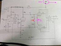
Measurement error, or.... your filter caps are totally dead. 420V DC comes from 300V(rms) of AC rectifier onto a filter capacitor. 300V onto a dead cap is 267V of very bad "DC".I only have 260 volts!
Besides this: It is preferable and more reliable to provide fixed cathode resistors of, say, 10 Ω each and to adjust bias via the voltages of both grids.
Best regards!
Best regards!
hi!!
Thanks, you misunderstood me! I want to repeat such a circuit, I can only use 260 volts! I need to change the values and value of the resistors!? how to change?? Is there a program where such a scheme can be inserted?
Thanks, you misunderstood me! I want to repeat such a circuit, I can only use 260 volts! I need to change the values and value of the resistors!? how to change?? Is there a program where such a scheme can be inserted?

WWOOOOOOO!!! ohhhh🤓
Thank you!!!It is fantastic. I will collect this!!! I will buy all the resistors!! thank you
Thank you!!!It is fantastic. I will collect this!!! I will buy all the resistors!! thank you
Last edited:
😀WWOOOOOOO!!! ohhhh🤓
Thank you!!!It is fantastic. I will collect this!!! I will buy all the resistors!! thank you
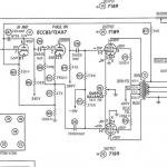
Please remember this is a simulation, not the real thing.
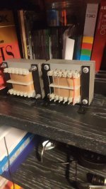
What kind of output transformer are you using?
For simulation I used a generic 8K typically used for 6BQ5 tubes.

- Home
- Amplifiers
- Tubes / Valves
- Need help designing BIAS circuit for old Bell amp