Get rid of all of those ceramic disc caps and it will sound a lot better!
I started to do that today with some polyester films that I have, then realized that they were not rated in the voltage...so an order for them will be next. I did an A/B comparison of the caps before going in and you are right, the ceramics did not sound all that good.
Update on it is that it is only getting better as the new caps are breaking in. Actually, the sound from it is quite exceptional for such a humble looking amp and the bias on all four tubes in staying even across all four output tubes, no matter how long the amp is playing.
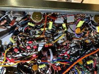
And to think this was given to me just for the iron and any other part that might be salvaged out of it.
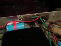
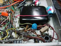
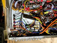
Last mods went in today, the Schottky diodes that were tricky since the case has to be isolated from the chassis or they short. Along with them, an additional 470 uF cap at the start of this negative rail. Voltage did not go up by much by replacing the old silicon diodes.
Also used the high filter switch to create a tone controls bypass using silver wire and .0047 coupling caps.
Tied in a blank 20 uF multisection can section in order not to waste it.
Replaced R31 and R65 with Takman Resistors.
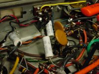
Got rid of a couple more ceramic coupling caps using some Orange Drops that I had from another project.
That is it for now, the sound and reliability are considerably improved. Thanks for the advise, pictures follow.
Also used the high filter switch to create a tone controls bypass using silver wire and .0047 coupling caps.
Tied in a blank 20 uF multisection can section in order not to waste it.
Replaced R31 and R65 with Takman Resistors.
Got rid of a couple more ceramic coupling caps using some Orange Drops that I had from another project.
That is it for now, the sound and reliability are considerably improved. Thanks for the advise, pictures follow.
Attachments
For the few wanting the daily update, here we go.
The 2440 played beautifully until bedtime last night. Some time during the night, the furnace broke down so the house was unusually cold this morning. Went to turn on the 2440 and it continued to blow fuses until it was obvious there was a hard short inside. I determined after removing all tubes and double checking all my work, that both Schottky (or shotty) diodes were not only blown but shorted inside. They were in full short mode with a 0 ohms reading. To the trash and out come trusty Radio Shack 1N4004. I don't know if it is my imagination, but these seem even quieter and no need to heat sink. Another hour or two and the unit is playing beautifully. Bias is rock steady.
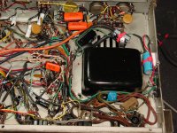
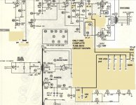
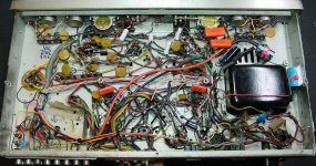
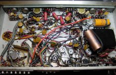
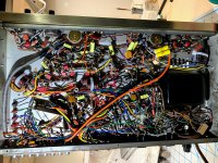
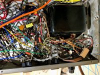
For posterity and the future Bell 2440, pictures of the final before and after shots, the diodes and extra capacitor, the schematics for the bias circuit and the tone bypass switch wiring.
A big THANKS to Craig of NOSValves for the design of the tube bias circuit, it works amazingly well.
Oh and the furnace, $220 later it works.
The 2440 played beautifully until bedtime last night. Some time during the night, the furnace broke down so the house was unusually cold this morning. Went to turn on the 2440 and it continued to blow fuses until it was obvious there was a hard short inside. I determined after removing all tubes and double checking all my work, that both Schottky (or shotty) diodes were not only blown but shorted inside. They were in full short mode with a 0 ohms reading. To the trash and out come trusty Radio Shack 1N4004. I don't know if it is my imagination, but these seem even quieter and no need to heat sink. Another hour or two and the unit is playing beautifully. Bias is rock steady.
For posterity and the future Bell 2440, pictures of the final before and after shots, the diodes and extra capacitor, the schematics for the bias circuit and the tone bypass switch wiring.
A big THANKS to Craig of NOSValves for the design of the tube bias circuit, it works amazingly well.
Oh and the furnace, $220 later it works.
Attachments
Last edited:
i am trying to find output transformers for this type of amp - do they have a number on them ? do you hVE A PHOTOFACT THAT MIGHT HAVE THERE MODEL LISTED ? with say the ohms at input - i suppose they could be anywhere from 2.8 k to 5 k ct. any ideas would be helpful . they look like they may be oversized transformers too like other bell circuits
i am trying to find output transformers for this type of amp - do they have a number on them ? do you hVE A PHOTOFACT THAT MIGHT HAVE THERE MODEL LISTED ? with say the ohms at input - i suppose they could be anywhere from 2.8 k to 5 k ct. any ideas would be helpful . they look like they may be oversized transformers too like other bell circuits
PM Sent...
For the few wanting the daily update, here we go.
For posterity and the future Bell 2440, pictures of the final before and after shots, the diodes and extra capacitor, the schematics for the bias circuit and the tone bypass switch wiring.
Thanks much for sharing this info; truly helpful and appreciated! I have a Bell 2420 (sort of a little brother / cousin, very similar but runs 6V6s). I too bypassed the tone controls but just hard-wired everything; in retrospect I should have used the Hi Filter like you did (it's also bypassed).
Oddly enough, I have two more Bells ready for restoration (I am a hobbyist, not a tech). One is a 2440, the other is a 6060. Thanks again for sharing, and no doubt I'll be posting here with head-scratchers once I get rolling!
EDIT: Since posting this, I reread the thread in its entirety; thanks for all the legwork and more importantly the sharing thereof! One thing I was not quite certain of however; did you end up using EL84, or EL84M? I actually have a quad of 7189A ready for the 2440, but it might be more forward-thinking to convert to EL84M if it can safely be done.
Last edited:
Slor,
JMO, sell the 7189A quad, as they are worth big $. The Russian 6П14П-EB (6p14p-ev), AKA EL84M, is tougher than old rubber boots. It's easily a genuine 7189 equivalent. Rewire the sockets to 6BQ5/EL84/7189 standards and put the Russian variant in. FWIW, I'd slightly reduce the power the O/P tubes are dissipating compared to OEM, to get good service life. The Russian tube rates to be in production, for the foreseeable future, and there is ZERO indication that 7189A equivalents will ever be produced again.
JMO, sell the 7189A quad, as they are worth big $. The Russian 6П14П-EB (6p14p-ev), AKA EL84M, is tougher than old rubber boots. It's easily a genuine 7189 equivalent. Rewire the sockets to 6BQ5/EL84/7189 standards and put the Russian variant in. FWIW, I'd slightly reduce the power the O/P tubes are dissipating compared to OEM, to get good service life. The Russian tube rates to be in production, for the foreseeable future, and there is ZERO indication that 7189A equivalents will ever be produced again.
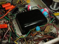
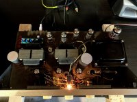
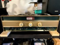
A couple more pictures now of the Bell 2440 in operation, bias is rock steady and sound is quite clean and nice...unlike before.
Hey whaleman, Awesome documentation! I’m a little curious about a few things before I would think about attempting this! We’re you able to run the bias low enough to use a standard el84 or did you just bring it low enough to get a little more life out of the recommended tubes?
I’ll be working on a 2440 in the near future and I’d like to be able to use a standard el84 but seeing as those are class A I figured I’m either stuck using only class a or only class b.
Again, thanks for the great write up
Be sure your DMM is set to VOLTAGE! To measure across the 10 ohm resistor for current measurement. for instants .30vdc would equal 30 milliamps or .25 would convert to 25milliamps That's why we love using 10 ohm & 1 ohm resistors in this spot. Beautiful amp and nice work...
The 7189A plate voltage, and 7189A screen voltage are very near to their maximum limit.
Do not use a 7189, their maximum voltages are rated much lower than the 7189A.
Putting 6BQ5, or EL84 tubes in there will Cook them.
They will not last.
If you want to use 6BQ5 or EL84 tubes, then modify the B+.
A pair of silicon diodes instead of the tube rectifier, add a very low capacitance first input capacitor, followed by an Input Choke (with at least critical inductance) will give you about the right B+ voltage. The added first capacitor ahead of the choke will probably range from 0.5 uF to 3uF to give a B+ voltage that will preserve 6BQ5 or EL84 tubes.
Or, make no changes, and be prepared to purchase a lot of $$$ 7189A tubes.
Last edited:
Boy!
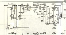
The right hand (modified) schematic in Post # 24 shows 410V on the Plate, 410V on the screen, and 0.8V on the 10 Ohm cathode current sense resistor.
0.8V/10 = 80mA (0.08A)
0.08A x 410V = 32.8 Watts.
Even if that was supposed to be 40mA per tube, that is 16.4 Watts.
That is way too much plate and screen dissipation for a EL34/6BQ5.
And way too much voltage for an EL84/6BQ5.
The schematic shows individual Fixed Adjustable Bias.
Ok, you can and should adjust the bias after the B+ modification.
As a first simple modification, get a 5 Henry 200mA choke, and connect it between the tube rectifier output, and the first filter capacitor.
Now you have a choke input filter, and a new B+ voltage of about 297V. Start with that, and adjust the bias potentiometers for 35mA or 37mA per EL84 or 6BQ5 tube.
35mA will make the tubes run cooler (10.4 Watts plate + screen dissipation).
Less power, but longer life.
You need to check if the pin connections of the 7189 are the same as the EL84/6BQ5.
I did not check the pin out. Even with the modified B+, it would be a disaster if the pin out is different.
you may have to rewire the socket connections.
I do not know where you can wire in the 4 bias pots, etc. and fit the 5 Henry choke, you may have to build an L bracket to put over the top.
You can figure it out. Do not mount the choke over or under an output transformer (Humm).
To start, and see if you like it, mount the choke externally first, and listen (be sure to ground the frame of the choke, and to use real good insulated wires to extend into the chassis.
Happy modifiying!
Happy listening!
The above are my suggestions.
Someone else may have other ideas.
Last edited:
Thank you for creating this thread whaleman. I recently found a good deal on a Bell 2440 that was in BAD shape but still salvageable. I decided on going the same route you did and mimicked your fixed adjustable bias circuit. Negative bias is matched and rock solid on all 4 output tubes. Speaking of which, I'm using a matched quad of 6P14P-EV I purchased on ebay.
I also did the tone bypass mod but I'm not sure if I did something wrong because even with the tone bypass on, the tone controls still work 😕. I'll keep messing with that later. Thanks again.
I also did the tone bypass mod but I'm not sure if I did something wrong because even with the tone bypass on, the tone controls still work 😕. I'll keep messing with that later. Thanks again.
The above are my suggestions.
Someone else may have other ideas.
I'd just add that these excellent thoughts apply to *all* EL84/6BQ5/7189 amplifiers from those days. Fisher's, Scott's, Dynaco's, etc. - all of 'em.
In their day, replacement valves were cheap, competition for "Watts!" numbers was intense, and AC power line voltages were lower. Today's perspective, for those of us restoring these old parties, is necessarily different.
YOS,
Chris
I also did the tone bypass mod but I'm not sure if I did something wrong because even with the tone bypass on, the tone controls still work 😕. I'll keep messing with that later. Thanks again.
No wonder. If you followed the schematics in #24, both tone controls still affect frequency response even with the switch in Off position. You need to completely take out the tone stack circuitry. A DPDT swith per channel (!) would do the trick.
If there's no way to install a four pole switch, you could connect the switches' wipers to the following stage and one end to the tone stack, the other one to a resistive divider that takes account for the stack's damping.
Best regards!
Thanks Kay. I realized this last night and temporarily wired it to bypass the tone circuit completely without the switch; just a straight wire with an additional .0047uf bypass cap. Gave it a good listening session and my wife actually prefers the ability to adjust the tone as she felt the highs were lacking. I think I'm just going to return it back to stock and replace the ceramics in the tone stack with some film caps.
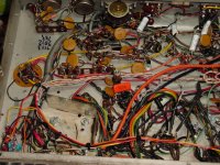
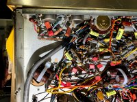
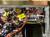
Going to leave some pics here for posterity. Found a cheap Bell 2440 in awful shape. Owner had it in on the garage floor with a towel on it and their cat used it for a bed. Yes, there was cat urine on it  . Gave it a spray with diluted simple green, brushed it, then rinsed with distilled water. Repeated that twice then blasted it with compressed air and let it sit in the patio to dry. Figured if it could survive that then it was worth doing the restore. Transformers and resistors tested good so I got to work. I replaced all the caps in the signal path. All electrolytic power caps replaced. Pots cleaned. Negative bias rectifiers changed to UF4007. The tall ceramic 20W 160R resistor in the bias circuit was dead and needed to be replaced. Modified the outputs to take 6P14P-EV tubes and performed NOSValves adjustable fixed bias mod. Got a little crazy and designed a custom pcb in KiCad. I have the output tubes biased to a rock steady 28mA. Amplifier sounds nice and I couldn't be happier. Thanks again to whaleman for starting this thread which happened to provide exactly what I needed.
. Gave it a spray with diluted simple green, brushed it, then rinsed with distilled water. Repeated that twice then blasted it with compressed air and let it sit in the patio to dry. Figured if it could survive that then it was worth doing the restore. Transformers and resistors tested good so I got to work. I replaced all the caps in the signal path. All electrolytic power caps replaced. Pots cleaned. Negative bias rectifiers changed to UF4007. The tall ceramic 20W 160R resistor in the bias circuit was dead and needed to be replaced. Modified the outputs to take 6P14P-EV tubes and performed NOSValves adjustable fixed bias mod. Got a little crazy and designed a custom pcb in KiCad. I have the output tubes biased to a rock steady 28mA. Amplifier sounds nice and I couldn't be happier. Thanks again to whaleman for starting this thread which happened to provide exactly what I needed.Attachments
@pelayostyle
Very nice work in bringing the "beast" back from the dead.
IMO, the next step is to modernize the source selection. I repeat a recommendation I've made many times. "Hard" wire a single set of I/P RCA females to the mag. level preamp, which is permanently configured for RIAA. Tape head I/Ps are passe in today's environment. Make all the other I/Ps "line" level.
If the OEM source selector switch is a complicated multi-deck affair, a Lorlin brand part from Mouser nicely gets things done.
I don't see a tape monitor loop switch on the front panel, but repurposing the lo, AKA rumble, filter switch would take care of that. Decent, modern, turntables are pretty darned good in the rumble dept. The hi, AKA scratch, filter could be useful, if 78 RPM records are to be played.
Owner had it in on the garage floor with a towel on it and their cat used it for a bed.
That's why I always say: Get rid of cats! I clearly prefer walking outside the house with our dog to have it peeing.
Best regards!
- Home
- Amplifiers
- Tubes / Valves
- Need help designing BIAS circuit for old Bell amp