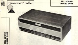
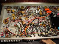
My brother gave me this Bell 2440 amp for parts, but I took pity and decided to restore it. Finally found the main problem, someone along the way decided to replace the 7189A tube (max plate voltage ~440 V) with EL84 / 6BQ5 (max plate voltage ~300). Common understanding has it that these tubes are interchangeable, but they are not.
Anyhow, the 7189A is scarce, so some Russian 6P14P-EB might do the trick, but BIAS current is still too high for the 434 plate voltage and are red plating upon power on. Funny thing, old stock 6BQ5 do not, but they will cook off eventually and this has been the history of this sad amp, that now has all new caps and no proper output tubes.
Has balance pots, but I need to add biasing pots in order to be able to use the Russian military tubes.
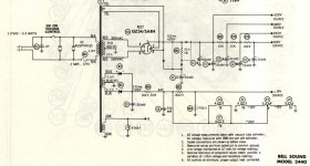
Help appreciated in designing retrofit bias circuit, which is beyond my schooling. I have attached the schematics and if anyone needs them for that matter, shoot me an email.
Anyhow, the 7189A is scarce, so some Russian 6P14P-EB might do the trick, but BIAS current is still too high for the 434 plate voltage and are red plating upon power on. Funny thing, old stock 6BQ5 do not, but they will cook off eventually and this has been the history of this sad amp, that now has all new caps and no proper output tubes.
Has balance pots, but I need to add biasing pots in order to be able to use the Russian military tubes.
Help appreciated in designing retrofit bias circuit, which is beyond my schooling. I have attached the schematics and if anyone needs them for that matter, shoot me an email.
Attachments


The Russian 6П14П-EB (6p14p-ev), AKA EL84M, is a genuine 7189 equivalent, which is quite tough. The schematic shows 7189, not 7189A. So far, so good. Unfortunately, the amp really is fixed bias and requires that all 4 O/P tubes be very closely matched in both cathode current and gm. A quick fix is to replace R82 with a 2500 Ω pot. and adjust the common bias voltage into the 23 or 24 V. range. That should stop the red plating, IF all 4 O/P tubes are properly matched. Jim McShane is good source for the matched quad and lots of other stuff.
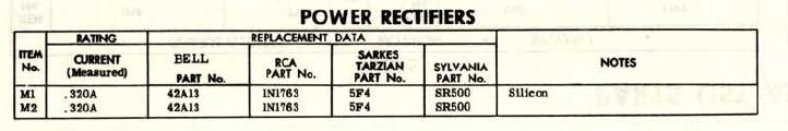
The OEM negative rail rectifiers should be replaced with 100 PIV/1 A. Schottky diodes. Some resistance may have to be added between the diodes and the filter, due to reduced forward drop. If the OEM parts are selenium, replacement is mandatory, as selenium diodes are ticking, toxic, time bombs. If the OEM diodes are silicon, they will be very noisy. Installation of Schottkys deals with both of the above matters.
If you are willing to do a rather complete rework, using a 5R4 as the B+ rectifier, instead of a 5AR4, will reduce the rail voltage by something around 50 V. If you exercise this option, use a "potato masher" 5R4 and hold the 1st filter cap. to 15 μF. Add a decent choke of several H. rated for 250 mA., after the 1st filter capacitor.
Alex,
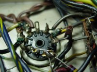
I got your email and figured why not just reply here. Do you actually have -19V at the control grids of the 7189 tubes? If so I suspect some other problem is causing the Russian tubes to red plate. Could you put up a picture of all 4 output tube socket wiring. I wonder if Bell used some of the empty tube pins as solder lugs on what may have been no internal connection pins on vintage EL84's but not on the Russian mil spec.
-19V should bias the Russian tubes low enough for them to not red plate.
This circuit would be relatively easy to change to individual tube adjustable fix bias like on the Scott amps you have worked on. Do you have room for 2 more trim pots or even better 4 in a row? The existing balance pots are not configured like what you are accustom to in the Scott amps you have worked on in the past so they will have to be changed or if you can install 4 new pots in a row 1 for each tube then the existing balance pot would be disconnected and the cathodes tied directly to ground VIA a 10 ohm resistor for measuring the bias of each tube.
Thanks Craig Ostby
www.nosvalves.com
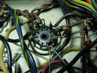
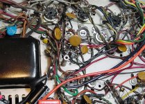
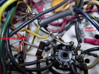
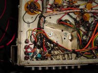
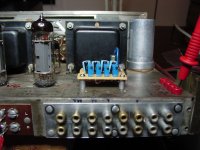
Thanks Eli and Craig for the informative posts. Eli, I did miss those 2 diodes, they are silicon and are attached in a picture. They are the 2 tan Hershey kiss looking things to the right of the transformer I believe (in the pic attached).
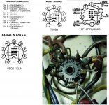
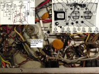
Craig, you are on the right track I think as far as pin wiring differences--and some nay-sayer will always chime in and spoil the party 😀 when people talk about these tubes being identical pin configuration (they might have reason, see attached).
It occurred to me late last night to compare pin configuration between all these tubes.
In the 6BQ5 and 6П14П-EB, the control grid 1 is energized by pin 2. In the 7189A, it does not matter since pin 1 and 2 are internally tied. In the Bell 2440, pin 2 is blank and pin 1 is used to provide the power to the #1 control grid. As a result, the 6П14П-EB tube as well at the 6BQ5 will run without it in the Bell 2440 and tend to eventually self destruct. The 6П14П-EB apparently immediately and the 6BQ5 wait until you walk out of the room.
The amp chassis calls for 7189A while the schematic calls for 7189, go figure.
So later today, I will tie pins 1 and 2 inside the amp and see where we end up.
The tubes I have are 6П14П-EP, the hardest ones I believe, a cryogenically treated matched quad set, and can't wait to put them to use.
As far as the voltage you asked about, I measured just under -19 volts (which is not making it into the 6П14П-EP tube because there is no wire on pin 2) so in reality 0 volts, and about 434 V at the plates.
Craig, let's hope I do not have to worry about a biasing circuit, because space is at a premium.
Attachments
Last edited:
Yup you have the problem figured out. Tie pin 1 & 2 together and the Russian Mil spec tubes will work like a champ!
Whaleman,
I'm glad you found the big flaw. However, you have observed what current higher average line voltages do to the B+ rail. As you measure the bias voltage as being low, getting the noisy OEM diodes out and a pair of Schottkys in will increase the bias voltage slightly and eliminate a source of noise. If out of spec., the bias voltage should be somewhat high not low.
All of the electrolytic caps. in the unit should be replaced, as they literally dry out over time. During the replacement process, increase the value of C3 somewhat and C4 substantially. Over 300 mA. is being drawn from the negative rail and the OEM filter values strike me as being inadequate. Remember, when the amp was new, capacitance per unit volume was nowhere near as large as it is currently.
If ceramic disc caps. are in the signal path, they should go in favor of either 716P series Orange Drops or Soviet surplus K40s. A mixture of those 2 cap. varieties could work out quite nicely. You get to hear the amp instead of a single dielectric. 😉
Yup you have the problem figured out. Tie pin 1 & 2 together and the Russian Mil spec tubes will work like a champ!
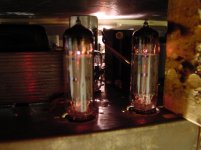
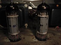
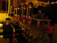
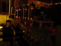
That was it! As soon as I soldered jumpers between pin 1 and pin 2 of the output tube sockets, the 6П14П-EP worked beautifully. No hum and no redplating of any kind. Matter of fact, they give off this really cool turquoise light from inside, you can kind of see it in the pics below. Glad it was a simple but hard to find solution. I also feel a bit better about throwing in some EL84 in once in a while now that they will be fully connected.
Whaleman,
I'm glad you found the big flaw. However, you have observed what current higher average line voltages do to the B+ rail. As you measure the bias voltage as being low, getting the noisy OEM diodes out and a pair of Schottkys in will increase the bias voltage slightly and eliminate a source of noise. If out of spec., the bias voltage should be somewhat high not low.
All of the electrolytic caps. in the unit should be replaced, as they literally dry out over time. During the replacement process, increase the value of C3 somewhat and C4 substantially. Over 300 mA. is being drawn from the negative rail and the OEM filter values strike me as being inadequate. Remember, when the amp was new, capacitance per unit volume was nowhere near as large as it is currently.
If ceramic disc caps. are in the signal path, they should go in favor of either 716P series Orange Drops or Soviet surplus K40s. A mixture of those 2 cap. varieties could work out quite nicely. You get to hear the amp instead of a single dielectric. 😉
Thanks for all this advise Eli, the diodes are next on the list. All electrolytics are out and C3 went to 220 uF and C4 to 1000 uF. I used some Orange Drop 716P caps on the loudness coupling, there were some paper caps there. The rest of the Red Chiefs got replaced with Mallory 150s though I might have had some K42Y Russians here, but are a bit large in size. The rest of the parts got the chemical treatments, though they hardly look like it. Played for four hours without a glitch, the cover will go on soon enough. It is dead quiet and sounding better every hour.
Thanks for the help and hope someone uses this information to restore another Bell 2440 in the future.
Attachments


Last edited:
Alex,
it might be prudent to equalize the resistance on the cathodes of the output tubes via that goofy balance pot in each channel. Then fire the amp up and measure the DC volts at the cathodes of all 4 tubes.Then use Ohm's law to figure out what current each of those tubes are drawing.
If it was me I'd install an individual bias circuit in it with 4 miniature 15 turn pots. It would be a simple mod that would allow you to run EL84's with a bit more safety.
Alex,
it might be prudent to equalize the resistance on the cathodes of the output tubes via that goofy balance pot in each channel. Then fire the amp up and measure the DC volts at the cathodes of all 4 tubes.Then use Ohm's law to figure out what current each of those tubes are drawing.
If it was me I'd install an individual bias circuit in it with 4 miniature 15 turn pots. It would be a simple mod that would allow you to run EL84's with a bit more safety.
Thanks for the advise Craig, let's do it. I did equalize resistance between the pots before installing the tubes, once installed and powered up, I further balanced the cathode voltage between the two tubes, it was reading about 450-500 mVDC between each cathode leg and ground. The pots are not very good and do not allow micro adjustment, so the multi turn pots would be ideal.
So what you are saying is remove these 2 pots and install 4 individual multi-turn pots in their place? That would be very easy. I'd like to install everything accessible from top chassis unlike these...kind of like the HH Scotts.
Craig and I spoke and he mapped out a good individual output tube biasing circuit ranging from -15 up to -23 VDC recommended using 4 individual pots, also getting rid of the balance pots (which I already did) and fixing a 10 ohm resistor on the cathode to ground instead. Eli also recommended higher negative voltage earlier.
This is a necessary retrofit as even after the fix with pin 1 & 2, output tube V5 starts to red plate ever so slightly after 2 hours and measures almost twice as much at the cathode as the other tubes, while the other are topping 375 mV, this one is 650 mV and seems to creep up from there.
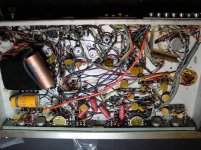
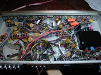
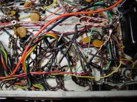
I thought the goofy balance pots were to blame so I replaced them with four 27 ohm resistors to simulate their center points, as in the picture, one is done while the other one is waiting removal. Even after this, the tube in V5 behaves the same way, I even swapped it with one on the other side and same behavior.
The negative bias voltage on V5, this problem socket, is the lowest of all four, somewhere around -17 VDC instead of the -19. Don't know why since all tubes feed off the same rail and the resistance of the 270K resistors are within 10% or so. The amp will sit until further work is done, do not want to damage any more tubes. I will draw the planned schematic change and upload it next.
This is a necessary retrofit as even after the fix with pin 1 & 2, output tube V5 starts to red plate ever so slightly after 2 hours and measures almost twice as much at the cathode as the other tubes, while the other are topping 375 mV, this one is 650 mV and seems to creep up from there.
I thought the goofy balance pots were to blame so I replaced them with four 27 ohm resistors to simulate their center points, as in the picture, one is done while the other one is waiting removal. Even after this, the tube in V5 behaves the same way, I even swapped it with one on the other side and same behavior.
The negative bias voltage on V5, this problem socket, is the lowest of all four, somewhere around -17 VDC instead of the -19. Don't know why since all tubes feed off the same rail and the resistance of the 270K resistors are within 10% or so. The amp will sit until further work is done, do not want to damage any more tubes. I will draw the planned schematic change and upload it next.
Attachments
Last edited:
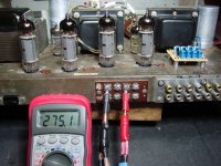
I caved in and wanted to listen to the amp, so I jumpered over the 270K resistor feeding negative rail voltage to V5 (so that the negative voltage would go up). It went up to a healthier -20.33 VDC and the cathode voltage went down to a safer .375 VDC. At this voltage we will not be seeing any redplating, though as noticed below, the cathode voltage is slightly different from tube to tube and matching them with the proposed circuit will be ideal. Some pictures of the jumper and the unit as it runs for measuring voltage follow.
The voltage on V5 did not creep at all even after 30 minutes as did before. Here are the measurements at pin 1,2 and pin 3 (cathode):
V6
-19.46
.299
V5
-20.25
.376
V9
-19.48
.420
V8
-19.49
.478
The voltage on V5 did not creep at all even after 30 minutes as did before. Here are the measurements at pin 1,2 and pin 3 (cathode):
V6
-19.46
.299
V5
-20.25
.376
V9
-19.48
.420
V8
-19.49
.478
Attachments
Last edited:
Whaleman,
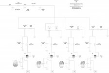
You're space constrained. Look before you leap. If you use 4X individual bias trim pots., you will need 5 (4X "hot" and 1 ground) tip jacks on the panel, along with the openings for the 4 controls. There is another way that consumes less space and could easily be better in the long run. Turn the excessive V. of the B+ rail to your advantage by employing combination bias. "Stand" each O/P tube pair on a 100 Ω/470 μF. network. That gives you a pair of test points, which reduces the count of new metal openings from 9 to 5. Matching requirements for each 7189 pair are close in gm, something that is always necessary, and only reasonably close in cathode current. The shared RC bias network will compensate for minor cathode current differences.
Let's say you want each 7189 to "idle" at 30 mA. Adjust the bias trim pots. to yield a 6 V. drop across the 100 Ω resistors.
BTW, as Jim McShane says, "be kind to your screen grids". Consider placing 100 Ω resistors in the B+ lines leading to them.
Whaleman,
You're space constrained. Look before you leap. If you use 4X individual bias trim pots., you will need 5 (4X "hot" and 1 ground) tip jacks on the panel, along with the openings for the 4 controls. There is another way that consumes less space and could easily be better in the long run. Turn the excessive V. of the B+ rail to your advantage by employing combination bias. "Stand" each O/P tube pair on a 100 Ω/470 μF. network. That gives you a pair of test points, which reduces the count of new metal openings from 9 to 5. Matching requirements for each 7189 pair are close in gm, something that is always necessary, and only reasonably close in cathode current. The shared RC bias network will compensate for minor cathode current differences.
Let's say you want each 7189 to "idle" at 30 mA. Adjust the bias trim pots. to yield a 6 V. drop across the 100 Ω resistors.
BTW, as Jim McShane says, "be kind to your screen grids". Consider placing 100 Ω resistors in the B+ lines leading to them.
Thanks Eli for the input, I think I kind of went in the direction of individual circuits for each tube. The good news on space is that I removed a pot at the inputs that freed up some real estate in a prime location. The components are miniature, so not much is needed.
Attached is the proposed schematic I drew up from conversation with Craig of NOSValves. The cathode bypass capacitor is my own contribution. Parts should arrive Thursday or Friday. Disclaimer: The 330 and 8200 ohm resistor values are only estimates.
Attachments
Last edited:
Forgo the 220uF bypass capacitors. They're not necessary. Add some insurance in case of wiper to track failure by adding resistors from -34V to each wiper. Of course you will have to re-calq your resistor values.
Wayne 😉
Wayne 😉
BTW that Bell 2440 you have there is a nice little amp. Back in the 1960-70s I had a Bell 2441 AM-FM-FM-MPX tuner that was built on the same chassis. Bell TRW was good for using up parts from other/older production runs. I also owned a Bell Carillon 6060 integrated amp in the same time period paired up with 2441. Both are resting peacefully somewhere.
...I also owned a Bell Carillon 6060 integrated amp in the same time period paired up with 2441. Both are resting peacefully somewhere.
That Bell Carillon 6060 is respected even today, they fetch around 4 digits. The cathode bypass cap is a good mod for keeping things stable, worth a try or so I read.
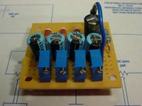
Phase 1 is done, completing the circuit on a circuit board that will sit on top of the chassis where a trimpot for the tuner input used to be.
The resistor values (8.2K and 330 ohms) worked the first time and I dialed the trimpots to just past mid-point at 6K ohms, the voltage was dead on -20.04 VDC with quite a wide range. Attached pictures of the apparatus.
Attachments


Last edited:
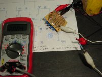
This little circuit works like a charm. I was able to dial all tubes to draw 27.5 mA with not too much effort and in the process I was able to get rid of some distortion from the output tubes running too cold in the bias.
The schematic calls for 32 mA draw, so I still have some room, though I think about a 6% decrease is in order to compensate for today's higher house voltages.
The best part is that there was no creep up on any of the tubes, so indication is that they are steady and happy.
I also got rid of some ceramic coupling caps as Eli recommended and totally forgot to bypass the cathode 10 ohms resistor, so it is staying out. I will post a listener report as I give the amp a bit of break in time. So far it is sounding quite nice and balanced L to R with real good tone and warmth.
BTW, to obtain the current draw, I use Ohms law as recommended by Craig.
.275 VDC / 10 ohm resistor at cathode = 27.5 mA or
I = V/R
Using this formula, I think I can ascertain the specified bias setting, at least for the original 7189A tubes:
1600 mV per channel / 50 ohm pot shared by both tubes = 32 mA (* 10 ohm resistor at the cathode, then measure 320 mV)
Some pics and yes, the sharpie writing will be replaced with proper labels and the amp does have a cover.
...and thanks for you'lls input.
Attachments

Last edited:
- Home
- Amplifiers
- Tubes / Valves
- Need help designing BIAS circuit for old Bell amp