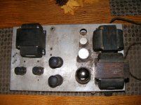
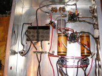
A few months ago I grabbed a 6L6 amp with a few 1950's vintage Hammond transformers. The OPT transformer isn't original as the cut wires lead (pun?) me to believe the previous OPT had pin connectors on the bottom ... maybe a 1700 series out of the same catalogue as these transformers on the amp:
275X60 Power Transformer: 400-400 volts, 135 DC ma, Fil 1 - 5v 3a ct, Fil 2 - 6.3v 5a ct
10-200X Choke - 10h, 200ma, 82 ohms, 800 max peak volts
1664 Output Transformer - 3800 ohms, 60 watts max, 4 8 15 30 250 500 ohm output
The 1664 OPT has a slightly different mount pattern from the original.
I took the time to sketch a schematic and have a few questions:
1) Does the circuit look feasible, ie safe to power up after I replace the caps and out of spec resistors, and resolve question 4).
2) The amp came with a (Made in Japan) HitRay 5U4 so is obviously not original, but I'm wondering with the 20uF first cap if it shouldn't be a 5Y3 rectifier.
3) Is there an advantage to increase the values of the 40uF caps?
4) I'm far from an EE, so am wondering where Pin 3 from the 6SQ7 should be connected. It is the black wire going to the OPT area.
There is an empty socket barely visible behind a transformer in the topside pic; it was for a remote on/off switch which I will be eliminating.
I know some of this old iron isn't made for 20-20k frequency range, but I plan on using this amp with a McIntosh MX113 (tuner/pre with mono output) to power a Klipsch HIP speaker for outdoor listening. If it sounds anything like a rebuilt Heathkit A-5A I once had I'll be happy.
Any help would be appreciated.
Tom
Attachments
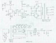
Drawing a proper circuit diagram instead of hiding details inside circles might help us help you.
You seem to have a lot of capacitance connected to the mains supply. Note that these must be X or Y rated, as appropriate. It is unclear whether you have a ground connection, or just a 2-wire supply.
You seem to have a lot of capacitance connected to the mains supply. Note that these must be X or Y rated, as appropriate. It is unclear whether you have a ground connection, or just a 2-wire supply.
You may want to check the positioning of the cathode resistor in the output stage. Also, I think that the grounding of the B+ might cause some smoke issues.
Drawing a proper circuit diagram instead of hiding details inside circles might help us help you.
You seem to have a lot of capacitance connected to the mains supply. Note that these must be X or Y rated, as appropriate. It is unclear whether you have a ground connection, or just a 2-wire supply.
You mean those little squiggles inside the circles mean something! LOL I'll fix that up and make corrections/verifications per SY's post. I spent 30+ years working with Architectural Drawings/Specs for high end commercial construction so there is a bit of a learning curve here. That's the first schematic I've ever drawn so please let me know what info is needed to convey the message.
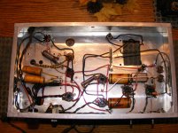
It's just a two wire twisted cable coming in through the chassis ... probably 1950's vintage!! You can see it in the picture of the top side. None of the wiring is frayed, cracked, or brittle; I know that doesn't make it safe to current standards though.
Pin 3 of the 6SQ7 is the cathode. The black wire goes to one of the speaker taps and is used for global negative feedback. Pins 4 & 5 of the 6SQ7 should be grounded.
You should show valve/tube symbols (with pin numbers added if you wish) rather than just numbered circles.
If that is your first schematic then well done!
Note that in audio it can be misleading to simply show lots of ground connections as the exact order and configuration of the grounds is important.
If that is your first schematic then well done!
Note that in audio it can be misleading to simply show lots of ground connections as the exact order and configuration of the grounds is important.
I'm thinking that the 6L6 plates (the CT on the OPT primary) should be connected to the power supply directly after the choke. The screens of the 6L6 tubes and the plates of the other stages should be connected to point 'A' of the supply.
On the 6L6's, it's wise to keep the screen voltage slightly lower than the plate voltage.
This is especially true with current-production tubes.
On the 6L6's, it's wise to keep the screen voltage slightly lower than the plate voltage.
This is especially true with current-production tubes.
I think that the grounding of the B+ might cause some smoke issues.
Still, that's the ultimate in low noise supplies.
My CFO (wife) is in the building so I can't bring the amp out ... too many of these projects follow me home and she gets mad when she sees a 'new' one. That is until she hears it!! 😀
I'll be replacing the .15/600 caps at the mains with an X2. With my Architectural background I don't think I took any shortcuts with the grounds; I think I drew them in the sequence in which I saw them ... unless I made a mistake which is entirely possible! On Architectural dwgs things are shown more or less generically but to scale, then Details, Schedules, and Specifications fill in the information ... a similar concept to a parts list. The numbers inside the circles are the pins, but I will add the squiggles as I would like to learn how to properly draw components/schematics. Just have to wait for the CFO to disappear to revise the drawing.
In the mean time I've been scrutinizing the pictures:
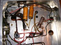
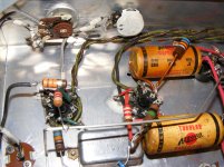
Sorry, the connection s/b cathode to cathode, then the 150 ohm resistor to ground. I may have done a bad thing in the PS area ... I assumed the octal socket went to a switch. See the 'Bottom 2 Power Supply' pic as the red wire goes from the 150 ohm resistor to the octal socket (and a small wire goes from the same leg of that 150 ohm resistor to the 40uF cap) and returns as the black wire to ground. The other two wires on that octal socket are 6.3v.
With all these OPT taps would the 15 ohm be suitable? What cap/resistor values would be a good/reasonable? starting point?
Pins 4 & 5 aren't currently grounded, but I will do so.
This is fantastic how all these minds can come together to work on this project, probably some 50-60 years after it was started.
Thanks,
Tom
I'll be replacing the .15/600 caps at the mains with an X2. With my Architectural background I don't think I took any shortcuts with the grounds; I think I drew them in the sequence in which I saw them ... unless I made a mistake which is entirely possible! On Architectural dwgs things are shown more or less generically but to scale, then Details, Schedules, and Specifications fill in the information ... a similar concept to a parts list. The numbers inside the circles are the pins, but I will add the squiggles as I would like to learn how to properly draw components/schematics. Just have to wait for the CFO to disappear to revise the drawing.
In the mean time I've been scrutinizing the pictures:
You may want to check the positioning of the cathode resistor in the output stage. Also, I think that the grounding of the B+ might cause some smoke issues.
Sorry, the connection s/b cathode to cathode, then the 150 ohm resistor to ground. I may have done a bad thing in the PS area ... I assumed the octal socket went to a switch. See the 'Bottom 2 Power Supply' pic as the red wire goes from the 150 ohm resistor to the octal socket (and a small wire goes from the same leg of that 150 ohm resistor to the 40uF cap) and returns as the black wire to ground. The other two wires on that octal socket are 6.3v.
Pin 3 of the 6SQ7 is the cathode. The black wire goes to one of the speaker taps and is used for global negative feedback. Pins 4 & 5 of the 6SQ7 should be grounded.
With all these OPT taps would the 15 ohm be suitable? What cap/resistor values would be a good/reasonable? starting point?
Pins 4 & 5 aren't currently grounded, but I will do so.
This is fantastic how all these minds can come together to work on this project, probably some 50-60 years after it was started.
Thanks,
Tom
Last edited:
I apologise in advance. Is your Life Insurance paid up. Your wife may need it.
One finger in the wrong place and this amp will do its best to KILL you. Get a professional in on this.
One finger in the wrong place and this amp will do its best to KILL you. Get a professional in on this.
The squiggles are the valve electrodes (e.g. cathode, anode). We think in terms of electrodes, not pin numbers. You only need pin numbers when you build it, not when you design it.
I apologise in advance. Is your Life Insurance paid up. Your wife may need it.
One finger in the wrong place and this amp will do its best to KILL you. Get a professional in on this.
So we should kill the professional?? YOU have no idea about my qualifications or experience. Why, I've even stood at the front of a Dodge while it was running and didn't get hit by a flying fan. And I've changed tires on my 1949 Chev truck with two piece rims only to tell the tale! I even touch the steel bumper of my 68 Pontiac while holding the positive terminal of the battery to check for voltage leaks. What I won't do though (if I smoked) is smoke near a car battery as they can explode.
Thanks for the concern, but I enjoy the challenge. I'm not a big believer in dumbing down society ... learn how to respect danger and go from there.
A few months ago I grabbed a 6L6 amp with a few 1950's vintage Hammond transformers. The OPT transformer isn't original as the cut wires lead (pun?) me to believe the previous OPT had pin connectors on the bottom ... maybe a 1700 series out of the same catalogue as these transformers on the amp:
275X60 Power Transformer: 400-400 volts, 135 DC ma, Fil 1 - 5v 3a ct, Fil 2 - 6.3v 5a ct
10-200X Choke - 10h, 200ma, 82 ohms, 800 max peak volts
1664 Output Transformer - 3800 ohms, 60 watts max, 4 8 15 30 250 500 ohm output
The 1664 OPT has a slightly different mount pattern from the original.
I took the time to sketch a schematic and have a few questions:
1) Does the circuit look feasible, ie safe to power up after I replace the caps and out of spec resistors, and resolve question 4).
No. You need to go back to the drawing board, and prepare a more accurate schemo. You don't show how the VTs are actually connected. You show a PS diagram that can't possibly work. The whole DC rail is paralleled with a 160R resistor, and the plates of the 6L6s are at DC ground. Wire it like that, and something is gonna poof.
2) The amp came with a (Made in Japan) HitRay 5U4 so is obviously not original, but I'm wondering with the 20uF first cap if it shouldn't be a 5Y3 rectifier.
A 20uF reservoir capacitor looks about right for a 5U4GB power diode. Given the stated current demand, a 5Y3 would be stressed, more than a 5U4GB.
3) Is there an advantage to increase the values of the 40uF caps?
For this design, It's doubtful.
I know some of this old iron isn't made for 20-20k frequency range, but I plan on using this amp with a McIntosh MX113 (tuner/pre with mono output) to power a Klipsch HIP speaker for outdoor listening. If it sounds anything like a rebuilt Heathkit A-5A I once had I'll be happy.
Any help would be appreciated.
Tom
I wouldn't expect much from this. It looks like a bargain type amp, nothing special.
Lastly, I would get rid of those capacitors in the AC lead. That is just asking for trouble. If one should short, the whole chassis becomes "hot", and represents a nasty shock hazard. Those "death caps" negate the whole purpose of an isolating PTX. Back in those days, they weren't as concerned with safety issues as they should have been.
For impulse suppression, it's better to parallel the whole secondary with a 0u01 / 3KV capacitor. That way, there is no possibility of a hot chassis. I would also strongly suggest a third wire ground of the chassis itself. It's barely effective as an audio frequency ground, but that's not the point. The purpose is to avoid a hot chassis.
I think the consensus is ... scrap the project. I may have made a drawing mistake here and there, but I didn't leave out any of the circuit so it would seem this was a partially completed project. I got it at a Hamfest so who knows what the history is. It cost me far less than what the metal 6L6's are worth ... and that's not much!! LOL
With that being said, I would still like to recycle it into an amp for outdoor listening. I know that hifi isn't the order of the day, but surely I think we would enjoy it more than our So NY ipod dock. Last summer I was using one of my restored Dynaco mkIII's, but that always made me nervous.
I had a look in the back of my RCA RC18 tube manual for an amp. The one 6L6 amp in there uses different spec transformers so even if it would work, it's past my capabilities to make it work. And it has tone controls, which I'm not a fan of. I would rather roll tubes to get the sound I'm after.
I'm wondering if someone might have a simple mono 6L6 (not 6L6GC) amp schematic using these transformers, 6L6's, and octal driver tubes (I have 6SN7, 6SL7, 6SQ7, 6BL7, 6BX7, 6C5, 6J5 tubes on the shelf):
275X60 Power Transformer: 400-400 volts, 135 DC ma, Fil 1 - 5v 3a ct, Fil 2 - 6.3v 5a ct
10-200X Choke - 10h, 200ma, 82 ohms, 800 max peak volts
1664 Output Transformer - 3800 ohms, 60 watts max, 4 8 15 30 250 500 ohm output
I sure there are some with far more knowledge than I that would consider this a waste of time, but I'm trying to learn something and the only way to do that is get your hands dirty. At least it won't hurt my wallet if something goes poof, and I'll keep my free in the other pocket!! LOL
I've looked around the internet, but there is too much info out there for me to filter out, and in some cases I've seen such comments as 'that circuit won't work' for whatever reason, so I may see something simple to build but it won't in fact work. I already have one of those!!
Thanks,
Tom
Gordon W over at AK suggested the following:
Bricktop's W4-AM
That would work for me. I'll ask over at AK to confirm my parts will work with this design.
Thanks,
Tom
Bricktop's W4-AM
That would work for me. I'll ask over at AK to confirm my parts will work with this design.
Thanks,
Tom
I rely on the software called "VISIO" to draw schematics. It's mostly drop & drag. Has tubes too. Been using it since it came out back in '93.
Read read read, you will most likely pick up most everything you need to learn from many experts. Been reading here forever, finally registered...🙂
Regards,
Doug
Read read read, you will most likely pick up most everything you need to learn from many experts. Been reading here forever, finally registered...🙂
Regards,
Doug
Thx Doug, didn't think of that. I taught myself to use the basics of AutoCAD ... I managed a staff of draftsmen so they helped me along when I was stuck. Been around it for decades since it was a DOS program with floppy disks and tablets. I'll check around to see if A/C has the necessary plugins. If not, I'll check into Vizio.
Electronics Projects - Vacuum-State Electronics
scroll down about half way and look at the "6V6 Stero Amp", it will take 6L6 tubes as drawn, but you may want to bias to your voltage & current. Sounds very nice with 2 6SL7's in guitar service..But works very nice with all octal tubes, with 2 each 6SN7 & a pair of 6V6 or 6L6 finals.
Visio is the simplest and fastest, for me. Has title blocks as well. It became popular early on as an export saving monster that would save not only to AutoCAD, but every other format you could think of.
Doug
- Status
- Not open for further replies.
- Home
- Amplifiers
- Tubes / Valves
- Need help completing vintage 6L6 amp