Hello, I'm building a class D amp that can be used in a car as a school project. So, the input is 12Vdc, output is 20Hz-20kHz, and I'm trying to get as much power coming out of it (hopefully 30W). For amplification, I'm using the H-bridge topology. Right now, I'm getting cross over distortion, and I don't know how to get the MOSFETs to get some dead time, so both MOSFETs will never be on at the same time. Attached is how the H-bridge looks like, any help is appreciated. Thanks.
Attachments
Hi
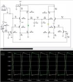
I don't know how I would do it, but see how I have it done...
4070 is my inverter to get + and - signal for IR. Dead time is made with RCD circuit between 4070 and IR... but in your case I have no idea how to add dead time...it is too early in the morning
I don't know how I would do it, but see how I have it done...
4070 is my inverter to get + and - signal for IR. Dead time is made with RCD circuit between 4070 and IR... but in your case I have no idea how to add dead time...it is too early in the morning
Attachments
munky!
With the smallest modification: much higher base resistance, faster transistors with lower beta!
With the smallest modification: much higher base resistance, faster transistors with lower beta!
With 12V DC supply voltage theoretical undistorted maximum output power is Vdd*Vdd/(2*Rl)=144/8=18W (@ 4 ohm). Do you use 2 ohm speaker?
Hi, Munky,
You can try put R on emitors of Q3-4-5-9 to define voltage drop accross 100ohm R (RC/RE=voltage gain = Vgs) Usually about 10V.
You can try put R on emitors of Q3-4-5-9 to define voltage drop accross 100ohm R (RC/RE=voltage gain = Vgs) Usually about 10V.
Hi Munky
if you drive direcly the P-mos with the same signal as the N-mos you will always have cross conduction.
The only way to avoid it is to introduce some dead time, ie a small amount of time where neither the P-mos nor the N-mos will conduct.
In an implementation like yours the easiest way is to use two comparator in place of U2E.
The inverting inputs of the two comparators must be set to two slightly different DC levels. The voltage difference between the two levels will set the amount of dead time.
The output of the first comparator will drive Q2 and Q8 (at the same time) the output of the second comparator will drive Q1 and Q7.
What is your PWM frequency? The output filter sounds strange with only 2uH of inductance. To do this filter design a 2nd order low pass filter with a cutoff of around 25-30Khz when loaded with 2ohm (you are running in full bridge so every side of the bridge sees the half of the total load impedance).
If you are doing this project just to learn something about class-D it is ok but I suggest you to use a dedicated mosfet driver IC to simplify the things and make it more reliable.
Your discrete gate driver scheme is not suitable for audio class D. Consider hi/low side driver ICs.
Since it is only 12 V AND complementary you could also use low-side-only drivers.
Regards
Charles
Regards
Charles
Probably not....
Like what others have said the thing you are trying might be done in a better way...
However, having had a look at your circuits and being an old fart it reminded of this one.
http://focus.ti.com/lit/an/slua137/slua137.pdf
Yah yah yah, it is a DC motor controller and therefore plorp but the whizz gives a circuit good to a whole 30KHz that might plug in with what you are trying to do.
DNA
Hello, THANKS for all the replies, I've tried to implement the circuit according to what you guys have told me. When I've added the resistors to the emitters of the transistors, the response is not squre anymore, will that cause a big problem? At least it improved the switching. I haven't tried the comparator idea yet, will do that very soon. Also, I made a very stupid mistake, I'm using a 4ohm speaker, so I should of put 8ohm load. Sorry for the confusion. By the way, for the project, I'm only allowed to use discrete components, so that's why I didnt have any high side/ low side driver ICs. Attached is the output with the resistors on the emitters. I will try the other ideas given to me really soon, and will keep you up to date. Thanks for the help, I appreciate it.
Attachments
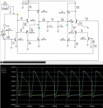
mag said:What is your PWM frequency?
The PWM frequency is 170kHz, so I just rounded it up to 200kHz in the hbridge circuit.
mag said:use two comparator in place of U2E
I'm not too sure on how to put the comparators, so one is after the inverter, but what is it comparing with? Is the other comparator just right after the first one? Sorry, I'm a little slow on this.
Hi Munky,
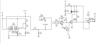
look at my schematics.
It is just a suggestion, not a real schematics.
I have changed the mosfet gate drivers with push-pull BJT pairs to
have fast turn on and turn off of the mosfets.
If you are using a 4ohm speaker you should put a 4ohm load for simulations.
Every half of the H-bridge will see 2ohm impedance towards GND, so the output filter shall be designed coordingly. In my shematics you will find an output filter with 30khz cutoff when loaded with 2ohm (ie with a 4ohm speaker).
Two comparators are used to drive the two branches of the H-bridge, they receive the same input signal but two different triangle wave ramps. One of the two ramps is shifted trough a constant offset voltage (V_offset) allowing to implement dead-time.
The fact that now the waveform are no more square is probably because you are driving the mosfet gate too slow.
Attachments
Sorry for the mistake in the shematics,
of course you need to put an inverter between the lower left
mosfet and the upper right mosfet gate drive...
The same applies in the other direction.
of course you need to put an inverter between the lower left
mosfet and the upper right mosfet gate drive...
The same applies in the other direction.
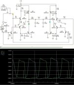
As mag said, 2 uH is too small!
I don't know why did you change Rl to 8 ohm!
You don't have to slow down switching, it was already too slow!
I also don't know what do you want with these measurements. Where do you suppose to see the existence of dead time? And what do you measure actually? Y Axis is scaled in volts, and it seems to be real, but you have written I2_2 and I1_1 (currents) next to the curves.
Dead time is invisible with these measurements! Dead time means that Q1 have to switch off before Q2 switch on. You have to watch drain voltage of Q1 and gate voltage of Q2, or drain currents! Time relation between A and C is not really important!
- Status
- Not open for further replies.
- Home
- Amplifiers
- Class D
- Need Help: Class D Cross Over