I designed a power supply for headphone amp which take 5v from usb, use lm27313 to generate 5.4V then go to LM27762 to have +/-4.7V. It works at some extends as it generate +/-4.7V well but the LM27762 seem to upset LM27313, it oscillated and can clearly see at noise spectrum at 6k, 12k ... I Change LM27313 to LP5907 4.5V and it also has this problem, disconnect it from LM27762 and use resistor as load it work just fine, so the problem must come from lm27762. I also tried disable negative part of LM27762 and the ringing of pre-reg is also gone so must be the charge-pump inside LM27762 upsets pre-reg some how.
Here is picture of noise spectrum of pre-reg LP5907 4.5V when supply to LM27762:

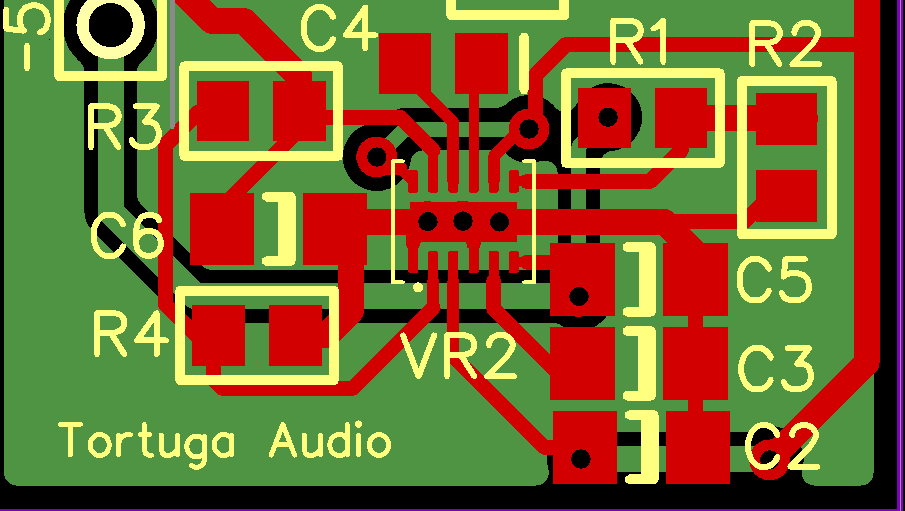
This is layout of the LM27762:

But it also strange that before i have made another LM27313 + LM27762 as this one but the two is very near each other and it works fine without oscillation

Hope some one can help me check on this 🙁
Here is picture of noise spectrum of pre-reg LP5907 4.5V when supply to LM27762:
This is layout of the LM27762:
But it also strange that before i have made another LM27313 + LM27762 as this one but the two is very near each other and it works fine without oscillation
Hope some one can help me check on this 🙁
I'm starting an eval of the LM27762 for a +/- 4.9V supply powered by 5V from an upstream SMPS CUI drop-in 7805 type regulator.
Not far enough along to answer your question regarding oscillation but I'm curious to why you felt the need to use 5.4V input to the LM27762 for +/- 4.7V output? My understanding is the dropout on the LM27762 is around 50 MV so using the USB 5V would be more than sufficient and you could avoid the additional boost regulator.
Cheers,
Morten
I'm starting an eval of the LM27762 for a +/- 4.9V supply powered by 5V from an upstream SMPS CUI drop-in 7805 type regulator.
Not far enough along to answer your question regarding oscillation but I'm curious to why you felt the need to use 5.4V input to the LM27762 for +/- 4.7V output? My understanding is the dropout on the LM27762 is around 50 MV so using the USB 5V would be more than sufficient and you could avoid the additional boost regulator.
Cheers,
Morten
It's because i first power the LM27762 with direct 5V USB but it oscillate then before i have another project which use lm27313 and lm27762 and it worked fine then i switch to it. Why 5.4V to 4.7V just because that's resistor value i have in hand, if it work i will change output voltage to near 5V to get maximum headroom.
I also found the problem after re-read datasheet carefully, when draw minimal current, lm27762 charge pump will enter discontinue mode which switching frequency can be in range of few Khz. So i add a load resistor, at > 20ma, the buzzing is gone.
I thought thats the end of the problem but no, when i change another usb cable, it oscillate again, only 1 of my cable work without problem.
Thanks for the background. I don't have a functioning prototype yet so your history with the LM27762 is quite relevant. The fact that different USB cables make a difference makes me wonder if adding a (larger) 5V supply capacitor to the input might stabilize things but that's pure speculation.
Since I just finished doing initial layout around LM27762 I've tried to pay close attention to the layout guidelines in the datasheet. It emphasizes keeping everything on the top plane including the ground - minimizing vias etc. Below is what I came up with after going through a few iterations. Of particular note is that all ground connections are on the top plane and lead to the chip's thermal pad (which is ground). Only the thermal pad has vias to the bottom ground plane. My first iteration had ground plane vias all over the place but this last iteration eliminates all of those except at the thermal pad which is now acting as a single star ground point for the chip....and star grounds usually work well in my experience. Whether this has anything to do with your oscillation problems is unclear but I'll know in 2-3 weeks whether this works well or not.
Since I just finished doing initial layout around LM27762 I've tried to pay close attention to the layout guidelines in the datasheet. It emphasizes keeping everything on the top plane including the ground - minimizing vias etc. Below is what I came up with after going through a few iterations. Of particular note is that all ground connections are on the top plane and lead to the chip's thermal pad (which is ground). Only the thermal pad has vias to the bottom ground plane. My first iteration had ground plane vias all over the place but this last iteration eliminates all of those except at the thermal pad which is now acting as a single star ground point for the chip....and star grounds usually work well in my experience. Whether this has anything to do with your oscillation problems is unclear but I'll know in 2-3 weeks whether this works well or not.