Ok perry i tried both output driver boards in the test amp and they both worked fine.
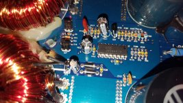
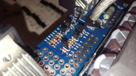
I included some better pics of the main board to help you do your thing lol.
I included some better pics of the main board to help you do your thing lol.
Attachments


Do you have the driver boards in sockets in both amps?
Could you have damaged vias where the driver board is/was soldered into the main board?
Could you have damaged vias where the driver board is/was soldered into the main board?
Yes they are sockets in booth amps and the vias look perfect and test good on continuity test from top to bottom of the mainboard. Only via that got alil damage was for the audio gnd pin on the ampere but its not bad and still is making a solid connection
Last edited:
You have the aq2200 diagram. Use it and the two amps (no driver boards installed) to confirm that you have a direct connection to all points that you should have (regulated voltage points, gate resistors...).
Have you checked L201 and L202?
Have you checked L201 and L202?
I will check L201& L202 and if there fine ill proceed with the aq2200 schematic and check all traces to the driver board and will post back asap!
Thanks for your time perry its much appreciated
Thanks for your time perry its much appreciated
Ok perry so i checked L201 & L202 they tested to be ok.
I also confrimed that i have a direct connection to all points that have (regulated voltage points, gate resistors... also compared to the other amp every via for the driver is spot on were it should be when compared to the hifonics bre2500d.
This amp truly has me lost everything seems to test and measure fine but with tbe driver board or outputs in the power light pulses and tbe tranformer for tbe 15v regulators and 5v regulators make a clicking sound when it dose it. However the transformer is seated very well and performs perfectly with the driver board out ive twisted and pull and got no change from the transformer or the 15v & 5v regulators but when tbe driver board is installed the voltages on tbe regulators seems to get pulled down to 6-7vdc coming from the winding.
The did have vibration damage and snapped mosfet legs so ima look for other broke connections on the main board because it seems like that is were the issue is.

Ok perry all connections are solid i also check tbe connections from the 15v regulators to tbe 5v regulators there fine.
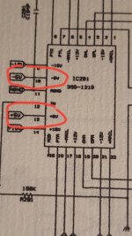
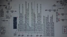
So i got the dwm1216 driver board pin layout print out from your tutorial and find i think there's some typos in it. It says pin 10 is for positive 5v regulator and pin 13 is for negative 5v regulator so after testing on continuity mode to confirm the 5 volt regulated voltage is going to the correct pins I found pin 10 is connected to the 5v negative regulator unlike the printout suggest after looking at the aq2200 schematic it confirms it is pin 10 for the five volt negative regulator and pin 13 for the positive 5 v regulator.
Which isn't a big deal but the reason I bring that up is because I thought the 5 v regulators we're in the wrong spots so I took them out of the bored and by doing this it allows the amp to power on with out tbe flashes which maybe be irrelevant but thought I should mention it.
Are you counting in the right direction?
Did you look at the input to the regulators to see if the input polarity corresponded with the output polarity?
Did you look at the input to the regulators to see if the input polarity corresponded with the output polarity?
Yes im counting correctly if the front of the driver board is facing me pin 1 is 1st on my left and pin 22 being the last on the right side of the board.
I checked to see if the output of the 15v regulators were going to the input of the correct 5v regulator and they were correct and they correspond with the aq2200 schematic thats why i gave you a heads up on tbe dwm1216 driver board print out pics below to help explain what i mean.
Sorry for the sideways pic but it keeps showing up like this even after editing it and flipping think the phone is acting up .
Attachments
Last edited:

Lol thats funny but your right i did print that a while back in 2012 i think not forsure but my last upgrade was in 2019.
Anyways i mite be on to something i think i mite have a leaky transistor im going to check and ill get back to you asap as always thanks for the help perry.
Anyways i mite be on to something i think i mite have a leaky transistor im going to check and ill get back to you asap as always thanks for the help perry.
Last edited:
Ok Perry it's not a leaky transistor I went ahead and changed all the small transistors in various protection circuits and Remote turn on still no change. The reason I thought it may be a leaky transistor was I was touching around on the board twisting capacitors Etc and the amp powered on and was working just fine after releasing the remote and hitting the remote again the amp was back to flashing off and on weird.
Just a few minutes ago I was trying to duplicate the same thing I did last night to see if I could get it to come back on with my oscilloscope Probe on the drain of the output mosfets the amp tries to oscillate but gets stuck it seems then the output mosfets run hot so I started to hit the remote pedal off and on repeatedly to see if that would do anything and the amp came on and started to work however now I can't get it to do it again LOL
Just a few minutes ago I was trying to duplicate the same thing I did last night to see if I could get it to come back on with my oscilloscope Probe on the drain of the output mosfets the amp tries to oscillate but gets stuck it seems then the output mosfets run hot so I started to hit the remote pedal off and on repeatedly to see if that would do anything and the amp came on and started to work however now I can't get it to do it again LOL
- Home
- General Interest
- Car Audio
- Need help ((ampere 2000.1D))