Recently, I had amplification and sound problem with my DIY Toccata Phono preamp. The amplification problem was due to I used a wrong JFET to replace the 2SK147 in the original circuit. I got some 2SK147 from China and put it into my amp, the current flow through the JFET is around 4.1mA and the amplification of the amp is improved but still weak. It is almost 20dB lower than my DIY EAR834P.
The sound is still terrible after I replaced the output capacitor from 0.47u to 2.2u, no treble and bass, only midrange.
>
> The original circuit has a volume control connected to the output capacitor. I replaced it by a 10K resistor. Will this cause the problem?
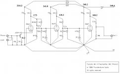
Attached the circuit with measured voltage, can anyone help?
The sound is still terrible after I replaced the output capacitor from 0.47u to 2.2u, no treble and bass, only midrange.
>
> The original circuit has a volume control connected to the output capacitor. I replaced it by a 10K resistor. Will this cause the problem?
Attached the circuit with measured voltage, can anyone help?
Attachments
I don't know this particular circuit, but two things strike me- the 4mA current in the fist stage seems awfully low. The 10k resistor load at the output seems likewise awfully low,
Hi Ky,
The K147 with -0.2V bias and 4mA is OK for K147BL (blue) grade part.
This is good news because there are many bad K147s for sale.
4mA is OK, but you can increase the current to get lower noise and more gain. Try the K147 source resistor from 50 to 33, or 27 ohm.
The main problem is the 10K output resistor. If you don't have a volume control here, you can go all the way up to 1M.
One way to get the best current in the K147 is to select the source resistor [the 50 ohm] until the K147 drain [=5842 cathode] is between 7 to 10V.
Do not operate the K147 with more than 14V here!
Do not operate the K147 with more than 14V here!
From the original Toccata Mk. II file:
http://www.fortunecity.com/rivendell/xentar/1179/projects/toccata/Toccata.html
"The Valve operates with the Grid grounded and provides around 3.5V to the FET to operate."
"The J-Fet must be selected for an Idss of around 10mA and be matched between channels."
http://www.fortunecity.com/rivendell/xentar/1179/projects/toccata/Toccata.html
"The Valve operates with the Grid grounded and provides around 3.5V to the FET to operate."
"The J-Fet must be selected for an Idss of around 10mA and be matched between channels."
Thanks for all gents' suggestion and advice. I will replace the output resistor to 1M and connect a VR to the source of the JFET to adjust the source current. Hope there will be improvement and will report later.
Thanks again for all your help.
Thanks again for all your help.
RF oscillation? High gain valves, no grid stoppers, possibly long cathode leads to the star points, no RF decoupling. Layout?
RF oscillation? High gain valves, no grid stoppers, possibly long cathode leads to the star points, no RF decoupling. Layout?
Hi QF96
I don't think there is any oscillation as the amplifier is very quiet. very low hum and noise.
I replaced the output resistor to 1M but without any improvement on the sound quality. Further adjust the source resistor of the JFET from 50ohm to 30ohm, the source current increased from 4mA to 5mA. There is no significant change on the amplification. The problem seems no so simple.
Hi QF96
I don't think there is any oscillation as the amplifier is very quiet. very low hum and noise.
Ky, There could be some high frequency [inaudible] oscillation that prevents the valves from amplifying normally.
Please check that you have resistors in the grid wire to each valve, mounted right on the socket. 2.2K to 10K will all work, but probably 2.2K is best for this circuit.
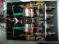
If that is not the problem, please post a photo of the wiring & layout.
Do your ears and loudspeakers work up to 100's of MHz? Mine don't.I don't think there is any oscillation as the amplifier is very quiet.
RF oscillation may sometimes appear as audio noise, but it is just as likely to appear as low gain and hard-to-pin-down distortion.
Two more basic questions: the problem is common to both channels? And what are measured heater voltages?
edit: You have a 39k and 26k resistor in parallel connected to the 417s. What is that?
edit: You have a 39k and 26k resistor in parallel connected to the 417s. What is that?
Most lead lengths look OK, apart from the long yellow ones tied to the big copper caps. What are they? Why are they tied? There seem to be an awful lot of tiewraps in the wiring. What was the thinking here? Generally, things should either be connected together or kept as far apart as possible to minimise stray capacitance.
Broad generalisation: the neater the wiring, the worse it is for RF. Why is RF an issue? You think you are building an audio amp, but the valves don't know that. If they see the right conditions they are perfectly happy to act as RF oscillators, especially if they are RF valves.
One quick check. Measure voltages again, but this time with a 1M resistor (or thereabouts) attached to the probe tip. You will have to scale the readings according to the impedance of your meter. This is often 10M, so scale by 11/10. Check against previous readings. Any difference? The idea is that the 1M stops the meter capacitance from damping any oscillation, so you see what is really happening.
Hi SY : the problem is common in both channels. Since I use CCS for heater, the measured heater voltage is around 6V. The 39k and 26k parallel resistor is the 34K plate resistor of the 6GK5.
Hi DF96 : the long yellow wires are the HT supply to the first and second stage. The only reason to tie everything together is to make things look tidy. Will cut all the tiewraps. I will check the voltage again follow your suggestion and report later.
Thanks.
Hi DF96 : the long yellow wires are the HT supply to the first and second stage. The only reason to tie everything together is to make things look tidy. Will cut all the tiewraps. I will check the voltage again follow your suggestion and report later.
Thanks.
- Status
- Not open for further replies.
- Home
- Amplifiers
- Tubes / Valves
- need help again on DIY Toccata MC Phono preamp