Hello folks,
I'm hoping one of you can help, I want to add an aux 3,5mm input to my system to use my mp3 devices/phone, but for the life of me I can't find where exactly the best place to solder in the L R and Grnd wires.
I don't want to start adding resistor and the like as i believe somewhere in the schems there should be a point at which i can just splice in the jack wires.
I was thinking of using the CD player route for the line as the player just skips and jumps even after a deep clean so it's not much use now.
Here's the schem if one of you could look at it and circle any points where i could do the splicing/addition that would be fantastic.
https://drive.google.com/file/d/0B4xzD8sj_yLBTTFQMTdEVlVsbG8/view?usp=sharing
All help greatly appreciated.
Breenconfed
A readable service manual may help you;
Download the Sony HCDH-7 manuals for free - Hifi Manuals
If you trace the analogue signal from your CD player, using a switched jack socket, you will be able to use the CD player (if you replace the laser assembly to get is working) when nothing external is plugged in or you AUX phone/MP3 etc.
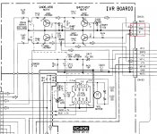
If you lift R235 and R236, they are at the point just before the mute transistors on the CD line (the IC side), feed them to the socket and return them after the switch contacts. The junction of R201 and R202 is your ground.
Download the Sony HCDH-7 manuals for free - Hifi Manuals
If you trace the analogue signal from your CD player, using a switched jack socket, you will be able to use the CD player (if you replace the laser assembly to get is working) when nothing external is plugged in or you AUX phone/MP3 etc.
If you lift R235 and R236, they are at the point just before the mute transistors on the CD line (the IC side), feed them to the socket and return them after the switch contacts. The junction of R201 and R202 is your ground.
at the input to the selector switch. This will probably be followed by the volume control. You could tap in here and just leave the 3.5mm empty when not in use.
Hello, thankyou for the info, I should have said in op that my knowledge on circuits is extremely limited. I can build a computer system and solder wires with some confidence but I don't understand the meanings of circuit board lingo.
However i did find where you were talking about and I do have some switching jacks.
All i really need now is the areas marked on where to solder exactly if you can edit the image here with solder points that would assist me very much.
Yes i admit I am an utter noob when it comes to identifying circuit board elements :/
Attachments
Ok new idea, what if I just soldered in on these, it would mean only 3 solder points but not sure if it would cause any other issues apart from being able to use it no matter what part of the stereo I was using.
Would this be an ok route?
Hoping it is, as i wouldn't need to take apart the system as that area is out in the open without any disassembly.
Would this be an ok route?
Hoping it is, as i wouldn't need to take apart the system as that area is out in the open without any disassembly.
Attachments
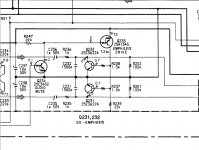
post5:the volume control. You could tap in here
C410 and the big black node next to "VOLUME" for one input pair.
C460 and the big black node next to "VOLUME" for other input pair.
You can use twisted pair, or coaxial, for the two input pairs.
NOTE !!!!!!
it is not a 3wire connection, it is a two wire connection for EACH input.
post5:
C410 and the big black node next to "VOLUME" for one input pair.
C460 and the big black node next to "VOLUME" for other input pair.
You can use twisted pair, or coaxial, for the two input pairs.
NOTE !!!!!!
it is not a 3wire connection, it is a two wire connection for EACH input.
Thankyou for reply, I can now get to work 🙂
- Status
- Not open for further replies.
- Home
- General Interest
- Everything Else
- Need help adding aux input to hifi system