Need a circuit for an attenuator with four steps,
to knock down the Line Level to mic. level for my camcorder.
I have 4 SPST toggle switches in the box, and
need 6, 12, 18, and 24db attenuation. I am thinking,
some sort of L-Pads but short out some of them?
Have lots of resistors 100-300 ohms, etc. in the drawer,
and lots of 6.8K and 10k etc
I can't seem to solve this... duh.
well -6db is half the voltage so 2 equal value resistors in series, one end is input the other end is ground and the middle is 6db down.
then if you split the bottomn resistor in equal values again and take the signal from that point it will be half again or 12db down, continue to get -18db and -24 db.
remember -6db is half voltage, -12db is quater -18 is 1/8th and -24 is 1/16th
so if the botomn resistor is 1ohm what are the rest?
then if you split the bottomn resistor in equal values again and take the signal from that point it will be half again or 12db down, continue to get -18db and -24 db.
remember -6db is half voltage, -12db is quater -18 is 1/8th and -24 is 1/16th
so if the botomn resistor is 1ohm what are the rest?
Or build four 6 dB attenuators in series. Of course, they'd all be loading one another... Tricky business. I think T networks are commonly used for this - at least in the RF world.
Multisync's idea is the one commonly used for audio. It's essentially a crude potentiometer - or voltage divider.
Multisync's idea is the one commonly used for audio. It's essentially a crude potentiometer - or voltage divider.

use a -6dB T pad attenuator.
The load impedance must match the attenuator impedance. This is easiest achieved by having a removable load on the output that can be swapped to suit different Rin values.
I built up 600r T attenuator for my 12 switch 0dB to -61dB attenuator in steps of 0.05dB. Great for accurately comparing different voltages, eg. input and output of a power amp.
a few problems you may run into,
what is the input Z of your mic input? 600ohms?
What is the level of the mic input 1-10 millivolts?
what is the output Z of your line device? 10Kohms or 1k ohms
what is the line out put level? 100 millivolts or 1volt?
you will have to know some of these values or make some guesses to get the attenuator to do what you want
The load impedance must match the attenuator impedance.
...AND the source impedance. Each attenuator pad input and output impedance must match the source and load impedances. Otherwise each attenuator stage looks back into an impedance which is modified by the source impedance.
You can design a single T- or pi-attenuator of any attenuation to match between any source impedance and any load impedance.
You can design a string of switched series T- or pi-attenuators to provide any desired attenuation steps between matched source and load impedances.
You cannot design a string of switched series T- or pi-attenuators to provide any desired attenuation steps between unmatched source and load impedances, as the second pad in the string may see the first pad as a source and vice versa. To maintain the calculated attenuation each pad must match its source impedance. If this is not the same as the load (output impedance of the preceeding pad) then the attenuation is affected. Of course if the only mismatch is to the source and each pad that is interposed has equal input and output impedances then this pulls the seen impedance closer to the correct value. This is why pads are sometimes used in RF design to minimise the impact of any mismatch.
For instance, you can design 6, 12, and 24dB L-attenuators between 50k and 50k. You can now switch them into and out of circuit (using a DPDT switch per stage) to give 0, 6, 12, 18, 24, 30, 36 and 42 dB attenuation (using a binary switching pattern) and both source and load will see 50k looking into the attenuator (or looking into each other) regardless. Each DPDT switch is wired to switch in an attenuator or a short. Make the source and load impedances different and the whole thing falls apart. It may well be possible to design a complicated arrangement of switches and resistors to achieve the desired result, but each pad must be modified in the switching to change its output impedance to be identical to its input impedance and this will change its attenuation which much again be corrected for.
If the source and load impedances are different you need to design 7 different T- or pi- pads (to match the range given above) and switch just one into circuit. Or modify the source or load impedance (or both) with a series or parallel resistor to make them identical (and accept any losses) and match the attenuator to this.
In this case the power is irrelevant as it is small enough, being line level, to be ignored.
This is all a bit nit-picking, you may well get away with something like this, or look at the link for values:

Attenuators : AMPLIFIERS AND ACTIVE DEVICES
w
Attenuator
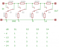
The attenuator circuit has input and output impedances 10K. It works fine in between my
cd-player (Marantz cd5003) and my amp which I built using LM3886. Each stage
has matched impedance with the previous and the next stage. This is the reason
why it has got the unusual resistor values. Actually it is part of the attached more
advanced attenuator.
Roushon
Attachments

Last edited:
Use two of them but do not connect the ground to any ground. Connect it between them. You will have to match the resistors to a good level, between both.
Gajanan Phadte
Gajanan Phadte
Thanks for your reply. So I don't need to halve the resistor values and place one resistor/2 in hot and one resistor /2 in cold? Im only talking about the series resistors, not the bridge resistors.
No.The attenuator circuit has input and output impedances 10K...........
The diagram is showing that when the output is loaded with 10k that the input impedance seen by the source is also 10k.
If the load were changed from the suggested 10k then the input impedance would no longer be consistently 10k.
But when looked at from the receiver end, the output impedance of this attenuator is NOT 10k.
Set Rs for the source to 200r. Set all the relays to 0dB. The load is still 10k. But looking back from the load to the output of the attenuator, the receiver sees a source impedance of 200r. The load sees Rs when set to 0dB.
Last edited:
Be careful.
To get the benefit of balanced impedance connections, the impedances matches MUST be VERY accurate. You must aim for much better than 1%. Usually 0.1% is accepted as the maximum tolerance, but benefits are to be found by achieving <0.01%.
It would be worth looking at typical switch resistances and how they vary, to see what effect, if any, these inconsistent resistances would have on the precision of your very accurately matched resistances and capacitances.
If I place this between a CD player (200Ohm output Z) and a line input (100K or higher Z) Will the attenuation be accurate within.. halve a dB? Between every step or in total, How should I look at this.. Thanks
This matching requirement will make it costly if low tolerance resistors are used. The audio source, if it is not a fully differential design, can be modded to accomodate a unipolar volume of your choice. This will give better results to maintain the CMRR of the setup.
Gajanan Phadte
Gajanan Phadte
Be careful.
To get the benefit of balanced impedance connections, the impedances matches MUST be VERY accurate. You must aim for much better than 1%. Usually 0.1% is accepted as the maximum tolerance, but benefits are to be found by achieving <0.01%.
It would be worth looking at typical switch resistances and how they vary, to see what effect, if any, these inconsistent resistances would have on the precision of your very accurately matched resistances and capacitances.
Not really... the original poster has an unbalanced source (which could start a whole different discussion) I like the russian design, though it really doesn't quite accomplish what it says it does. (just did the spreadsheet with combinatorial attenuation characteristics, using the Thévenin equivalent resistance and attenuated source voltage as the feed...) But its in the right direction.
With only 4 switches ... The resistor matrix would be much simpler, as only ONE switch at a time could be selected for attenuation.
OP: the formula you're looking for starts here:
dB = 20 log10( ratio ) therefore ratio = 10 ^ (dB/20)
You wanted ... 6, 12, 18, 24 db
The ratios would be 0.501, 0.251, 0.126 and 0.063 respectively
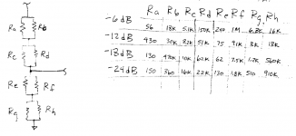
These in turn correspond to the following resistor pairs (to "kind of" match the 10K sink)
1K:1K -6 dB
1K:335R -12 dB
1K:144R -18 dB
1K:67R -24 db
Even figuring the 10K load into it (which will reduce output a bit more), the worst case is the -6 dB case, which becomes -6.4 dB... hardly worth worrying about. Its not as if you're building a precision instrumentation pad. You're building an attenuator for your CD player!
Which of course ... brings up the idea of just having a volume-pot (audio-taper) in a small project box, with the unbalanced IN, and a balanced OUT. Use a quality pot. Ground the MINUS pin of the balanced jack. The Pot should be relatively low value (1K, 2.5K or thereabouts) so as to minimize the effect of the 10K load on its attenuation. A nice knob and a carefully measured set of attenuation settings, and you have the best of both worlds - totally variable attenuation, and, calibrated set-points for your rig. Heck... once you got that together, you can then lay out (in Illustrator or equiv.) the reticle scale and use crafty DIYaudio techniques to transfer it to your project box.

GoatGuy
- Status
- Not open for further replies.
- Home
- Source & Line
- Analog Line Level
- Need circuit, 6,12,18,24db attenuator