Sorry, only in German but good illustration..
This would not apply to the present case.
What does apply here? My understanding is the same as JPS64.
Wide bandwidth op amps require the best possible hf bypassing to ground. Think about what the op amp sees.
Use a 0.01uF right at the pin (better than a 0.1uF for this case, a higher self resonant frequency),
then other cap(s) close. The physically large electrolytic can still be placed fairly close to the ps pin
to minimize the loop inductance. The further routing to the connector and externals is of no concern,
since that is a high inductance path.
The subject of bypassing is one that really interests me yet confounds me a bit as articles help to shed light on the subject but instead, cloud it. In some cases, I see where more than one cap is always recommended, and then it follows with an article from someone else who says paralleling caps does nothing and one is all you need next to the op amp pin.
After going through about 5 or 6 articles on the subject, I've found some consistency, including one recommendation that mirrored rayma's suggestion for this layout. Tonight, I've used Kemet's K-Sim online tool to play around with capacitor resonant frequency.
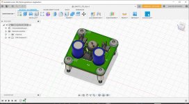
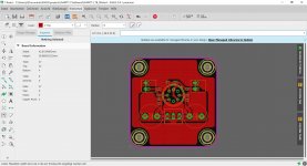
The consistent info I see most often is the focus on bandwidth, specifically on 50MHz or higher bandwidth op amps requiring a 100 nF smd cap but an even smaller value as well closest to the pin of the op amp. The recommendation I read was 10nF to 68 nF. Using the Kemet tool, I clearly see it matters on the size of the cap. I laid this out with all 1206 sized components, but smaller seems to be better, at least for the 10 nF parts. I realize that I will have to check the rail behavior with my scope once I have a prototype built.
This conversation has been interesting.
After going through about 5 or 6 articles on the subject, I've found some consistency, including one recommendation that mirrored rayma's suggestion for this layout. Tonight, I've used Kemet's K-Sim online tool to play around with capacitor resonant frequency.
The consistent info I see most often is the focus on bandwidth, specifically on 50MHz or higher bandwidth op amps requiring a 100 nF smd cap but an even smaller value as well closest to the pin of the op amp. The recommendation I read was 10nF to 68 nF. Using the Kemet tool, I clearly see it matters on the size of the cap. I laid this out with all 1206 sized components, but smaller seems to be better, at least for the 10 nF parts. I realize that I will have to check the rail behavior with my scope once I have a prototype built.
This conversation has been interesting.
At such high frequencies, the capacitor's physical dimensions matter more than the capacitance uF value. More than one small capacitor in parallel can be problematic, with multiple resonances. The esr of the electrolytic can be of significant value for damping; testing is best. And don't make bypass caps use vias, they should connect directly to the ground plane.
Last edited:
The board I laid out has a location for a .01 uF cap and .1 uF cap both next to the op amp supply pins. So is that bad since paralleling those two values will add resonances? BTW, I did see an article where the author showed the two resonances by paralleling the two caps. I figured my strategy would be to only solder one smd cap down, measure, and then if I'm lucky and it's stable, just leave it at that.
I did see an article where the author showed the two resonances by paralleling the two caps. I figured my strategy would be to only solder one smd cap down, measure, and then if I'm lucky and it's stable, just leave it at that.
Right, the second cap was for an option. http://www.ti.com/lit/an/sloa069/sloa069.pdf
Ahh, got it, ok. Thanks. I'll read up on the pdf. Boy, next time I work with an op amp,
I'll pick a more pedestrian version!
Watch for the trick of mounting the smt cap on its side.
I appreciate all the input and I'll enjoy going back through the thread when I layout alternate boards when I'm done with this one. Most likely I'll go with what Jan recommended so I can swap op amps, and I'll likely stay away some from such a wide bandwidth part in the future.
I'll read up on the pdf that rayma posted and downsize the cap size. I've also avoided low impedance electrolytics as it seems from my research into wide bandwidth op amps that a little resistance helps. I believe on other threads, others mention a low ESR part isn't always called for and this appears to be one.
I'll read up on the pdf that rayma posted and downsize the cap size. I've also avoided low impedance electrolytics as it seems from my research into wide bandwidth op amps that a little resistance helps. I believe on other threads, others mention a low ESR part isn't always called for and this appears to be one.
- Status
- This old topic is closed. If you want to reopen this topic, contact a moderator using the "Report Post" button.
- Home
- Source & Line
- Analog Line Level
- Need an opinion on layout of LME49713 preamp