Looks good but I would put the 150R resistor back. The value isn't critical at all, it will introduce negligible attenuation (unless the input impedance of the next stage is insanely low) and it will isolate the output of the opamp from any capacitance (parasitic, cable, etc.) that could make it unstable.
Cheers,
Cabirio
Cheers,
Cabirio
Could you Mooly draw me how to do , this two option ?
Another qeustion is ,Do you know if the JRC5532D is the same as TI 5532 ?
Sorry, I must have missed your reply somehow.
I think the 5532 question has been answered. Whether the JRC version is the same as TI, well I honestly don't know how the two would compare.
Your bias arrangement is fine but I would do as cabirio suggests and reinstate the series output resistor. The value isn't critical, anything over a few tens of ohms is sufficient. So 39, 47, 56 etc, all common values, any would be fine.

You *still* dodge the question about the huge attenuation shown before the preamp.
If you do not explain it, any waste of braincells analyzing the preamp becomes that, a waste.
Given such a huge attenuation, you do not need a preamp or gain, just a unity gain buffer, where *any* Op Amp will work wonderfully, simply attenuate a little less, to make up for the 2X/5X gain, making choosing one over the other a moot point.
Not sure what are you trying to achieve and you certainly don't state it.
Waste of time and bandwidth.
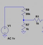
Then add a note saying so.do you mean to this ? thats the schema of the volume pot ..
That way we can see what you propose.
This is what you wrote:
It is no different with using series resistance. 10K-20K is a standard for low noise. But the source does indeed prefer high load impedance.
This reciever has a 100k volume pot , in front of it I put a 50K because the gain was too high
It is no different with using series resistance. 10K-20K is a standard for low noise. But the source does indeed prefer high load impedance.
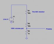
I should be more clear , you right guys . this how I set the 50K resistor .
Attachments
Last edited:
I should be more clear , you right guys . this how I set the 50K resistor .
Throw away that added input resistor.
Change the amplifying stage to a +0dB gain Buffer stage.
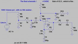
Throw away that added input resistor.I did so , please follow the last messages and see the final schema .
And change that pre-amp from a gain of +13.6dB to +0dB.
This is the final schematic , The 50k resistor is gone to rest in peace .. 😉
http://www.diyaudio.com/forums/anal...mise-my-opamp-preamplifier-2.html#post4702108
http://www.diyaudio.com/forums/anal...mise-my-opamp-preamplifier-2.html#post4702108
Attachments
Last edited:
Agree and add: IF that's your final design it has poor performance, sorry.
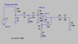
1) it is absolutely unrealistic to simulate a 100k volume pot set to such a low value as 1k :
a) it is not representative at all of any normal setting which will be found in normal use .
40dB attenuation considered a representative setting? WTF?
b) in any case, it's even very difficult to set; even minute variations of the volume knob position will have huge changes at such a low unrealistic setting, compounded by tendency of real world potentiometers to be quite far from indicated settings at such low rotation angles.
Carbon tracks show irregular jumps at such values, because wiper is getting close to the crimped terminals.
Clearly it's a simulated value (you can throw *any* value at a simulator and it won't complain) .
2) even if it could be set to such values, the 1k unrealistic setting only hides a fundamental flaw with the design you are ignoring: the huge 470pF to ground shown at the input.
To see its effect, imagine the pot set to "5" if Linear, to 7 or 8 if Log, meaning halfway the resistive value, so 100k pot means set 50k/50k.
The source impedance seen by your preamp is 50k/2 (since both halves are in parallel as far as a generator impedance is concerned) so your preamp sees a generator through a 25k resistor.
Now, what is the cutoff frequency if we have an input capacitor of 470pF across the input?
Do the Math, but just to simplify your life, here it is: your input network is 3dB down at very audible 13kHz .
With your earlier 50k resistor in series, and supposing it was set to 75k/75k so 37500 ohms generator impedance, we would have had an appalling 3dB cutoff at 9kHz .
Hi Fi went beyond that limit some 75 years ago 😉
Of course all this is hidden by the unrealistic volume control setting you chose, that's why everybody is unhappy with that.
- Status
- Not open for further replies.
- Home
- Source & Line
- Analog Line Level
- need advise to optimise my OPamp preamplifier