Bonjour Nicolas
If I were you I would not worry about the extra phase shift of a blocking cap. If the cap is part of the equalization, then yes: it will cause shift: with analogue (and IIR) filters there is no free lunch: every order of the filter adds another 90 degrees.
Furthermore, if you want to realize an acoustic 24dB/oct. LR roll off, usually electric filtering slopes of 12-18 dB are sufficient, so once your target is achieved you end up as intended. But the hard part is ending up with the acoustical slopes as intended. In-box measurements are mandatory here.
Unfortunately, the Douglas Self book, in itself a wealth of information on active filtering, does not contain a single real life loudspeaker tailored design.
Although you asked KSTR, I take the liberty to give you some sources for Fliege: http://www.ti.com/lit/an/slyt235/slyt235.pdf.
Active Filters
Good Luck,
Eelco
Elliott has some info : Active Filters EDIT: Boden won!What about state variable filters? Q, cutt-of frequency etc are manageable separatabely?
Could you give further information about Fliege filters?
He's showing highpass and lowpass as well, not only the standard notch. There's also bandpass and allpass configs.
Fliege is really flexible and low parts count for a filter with very stable and independant parameters.
There are issues one has to deal with :
- Stability, you'll always need a compensator RC around the opamp that doens't have the capacitive feedback, and that has to be tuned depending on opamp choice (also main circuit parameters might need to be adjusted to get to the target curve). I wonder why the textbooks never show this?
Clipping is rather nasty, and the textbook schemes often have severe headroom issues that remain hidden (e.g. in the textbook notch the lower opamp output is twice the signal). This can be tuned by changing the main divider ratio and/or by scaling the main RC differently -- at the cost of a change in resistor noise and/or OpAmp noise gain.
As ususal, play with circuits in the simulator and look what happens when you change values systematically.
Last edited:
My impression as well. Not his best book for sure.Unfortunately, the Douglas Self book, in itself a wealth of information on active filtering, does not contain a single real life loudspeaker tailored design.
Hello,
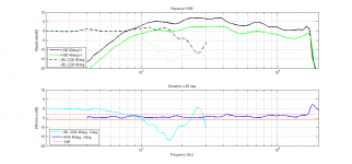
Found this on another forum : B&C DE250 + RCFH100
Is it really mandatory to compensate the HF losses?
Found this on another forum : B&C DE250 + RCFH100
An externally hosted image should be here but it was not working when we last tested it.
Is it really mandatory to compensate the HF losses?
Attachments
- Status
- This old topic is closed. If you want to reopen this topic, contact a moderator using the "Report Post" button.