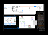
Hi All, I am working on a Project with another Member, and we are looking to build this amplifier. We are using the Old Transformers from a Wards Console SE amplifier. The notation on the Schematic shows the output transformers at 2.5k ohms, But this was pasted from another website. Our output transformers are 500 ohms Primary, 1 ohm secondary resistance. Now, looking at the Power Supply, the choke I have no Idea how to size it according to what's there, much less if it's in the right place. I need some guidance in coming up with a value. If you know of a value you would use please let me know, that would be appreciated. The other point is where would I hook up the Bias pot and Meter for each channel, If I were to do TubeCad's Fixed Bias circuit, I would need a -36v power supply correct? I am not sure of the voltages if they are correct, I was going by the Wards Schematic for that! Any advice on this amplifier would be appreciated VERY much!!! Lydia
Attachments
The 6CA4/EZ81 is good for 150 mA. of B+. Is that enough for 2 channels?
Unless you use current regulated DC to energize the 6B4 filaments, you are going to be driven insane by hum. If you want AC heating, use 2A3s.
Unless you use current regulated DC to energize the 6B4 filaments, you are going to be driven insane by hum. If you want AC heating, use 2A3s.
Our output transformers are 500 ohms Primary, 1 ohm secondary resistance.
Just a note: if these are DC multimeter resistance measurements, they are NOT the same as the AC impedance measurements and they do NOT give any indication of the transformer ratio.
jan
If you are going to have that 1K resistor in the B+ I would add in another cap if you have room then you could use a much smaller choke and get most likely even less ripple on your B+. Are you sure you want a 1K resistor in your B+? Seems a terrible waste of power.
Example if keeping the 1K resistor: 6CA4 => 33uF => 2H choke(or less) => 33uF => 1K resistor => 47uF => output trans.
Example if keeping the 1K resistor: 6CA4 => 33uF => 2H choke(or less) => 33uF => 1K resistor => 47uF => output trans.
If you have the choke and need a value for it, as Eli said it should be rated for about 150mA, look on this chart and check against the size/resistance of choke you have there. I would think you should get pretty close.
Hammond Mfg. - D.C. Filter Chokes - (153 - 159 Series)
Also if you are using cathode bias I would try to get as much voltage as possible to the anode of the 6B4G from your current power supply.
Hammond Mfg. - D.C. Filter Chokes - (153 - 159 Series)
Also if you are using cathode bias I would try to get as much voltage as possible to the anode of the 6B4G from your current power supply.
- Status
- Not open for further replies.
