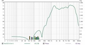
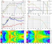
I working on designing a surround speaker using the Fountek NeoCD3.0 ribbon. It has a 7db hump from 10khz to 20khz and I'm not sure if I need to deal with it. I have been testing it with a DSP to help design a passive crossover. I have listened to it with a high self filter to flatten it out and I can't hear much difference, maybe the high end loses some sparkle, but honestly it doesn't sound bad without the high shelf. Now I admit I'm old and can't hear past 12-14khz so that is why I'm asking. Simulating the crossover in VituisCad a 100mh inductor in line with tweeter will get rid of the hump and because it is a low pass will not be self filter but a 6db per octave filter. Here is link to the specs for the tweeter and the hump clearly shows on axis in the plots. I have also attach my on access measurement
https://www.madisoundspeakerstore.c...3.0m-blk-3-ribbon-tweeter-round-flange-black/
https://www.madisoundspeakerstore.c...3.0m-blk-3-ribbon-tweeter-round-flange-black/
Attachments
I would take an interest in the response from the mid kHz going upward. Get it just right up to 10k, then worry about higher.
Even though the very high frequencies are not as audible, their behaviour can be even less critical if they don't fall into line with those below them.
Even though the very high frequencies are not as audible, their behaviour can be even less critical if they don't fall into line with those below them.
I was also suggesting that if you fix it without the lower frequencies being at their best, then it could possibly be harder to tell whether it is worthwhile.
In any case, yes that is the right way to fit a curve, and you have it covered far enough down.
By the way, it may be an on-axis problem. Issues on-axis have little relation to the overall sound because on-axis is a very small part of the overall coverage.
In any case, yes that is the right way to fit a curve, and you have it covered far enough down.
By the way, it may be an on-axis problem. Issues on-axis have little relation to the overall sound because on-axis is a very small part of the overall coverage.
Have you tried the recommended 2.5K 3rd Order?
I also assume you are trying the DSP with a cap inline for your testing as suggested?
I am just pulling this from the Madisound page.
Have you looked over tech-talk site and checked if anyone there has made a crossover for this driver?
I also assume you are trying the DSP with a cap inline for your testing as suggested?
I am just pulling this from the Madisound page.
Have you looked over tech-talk site and checked if anyone there has made a crossover for this driver?
I did try a 3r order at 2500hz, I thought I heard some distortion so I pushed it up to 3khz. The measurement in port 3 is a 3rd order passive that I tuned to make the LR4 at 3khz, it sounded better. This is all in a test box made mostly from corrugated plastic, so some of the distortion might very well be caused resonance. When I build the real enclosures I will try crossing at 2500hz again.Have you tried the recommended 2.5K 3rd Order?
I also assume you are trying the DSP with a cap inline for your testing as suggested?
I am just pulling this from the Madisound page.
Have you looked over tech-talk site and checked if anyone there has made a crossover for this driver?
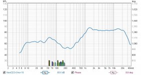
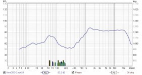
My plan is to use the tweeter both for two way surrounds and a MTM horizontal center. Attached are the following on axis frequency response charts for my test of the center, brown is the measured response of a passive crossover I put together out spare parts, blue is modeled in VituixCad and green is the same passive crossover with a .01mH inductor in series with the tweeter. Also attached is the XO and six pack.
Attachments

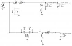
Just wondering why there are so many caps and resistors? Is it due to the resultant size when totaled out? Speaking of the ones running in series/parallel.
This is a test XO, I used what I have on hand to come as close to the calculated values. When I build the final XO I will order all the correct size which will limit the component count.Just wondering why there are so many caps and resistors? Is it due to the resultant size when totaled out? Speaking of the ones running in series/parallel.
I'm not experienced with the Neo 3CD, but the horn loaded Neo3CDh, which I think is the same motor and ribbon.
The horn loaded h variant exhibits some cavity resonance around 1500 to 2000Hz from an article (maybe K & T?), and I believe there was mention of the flat faceplate Neo3CD having similar cavity resonances
For those reasons I would not use it below 3kHz 3rd or 4th order, though I have run it in much less optimal crossovers.
Right now I'm crossing at 3K 3rd order, sounds better than the recommended 2500 3Rd order.I'm not experienced with the Neo 3CD, but the horn loaded Neo3CDh, which I think is the same motor and ribbon.
The horn loaded h variant exhibits some cavity resonance around 1500 to 2000Hz from an article (maybe K & T?), and I believe there was mention of the flat faceplate Neo3CD having similar cavity resonances
For those reasons I would not use it below 3kHz 3rd or 4th order, though I have run it in much less optimal crossovers.
I was going to edit and ran into the time limit.Right now I'm crossing at 3K 3rd order, sounds better than the recommended 2500 3Rd order.
To be honest and fair the ribbon is a lovely thing, but anything sub 2500Hz needs cutting sharply. 3kHz 4th order is more close to reality than the datasheet recommended circuit.
It is even better crossed slightly higher, 3.5 to 4kHz.
The rise between 10k and Ultrasonic-ville, can be easily dealt with using a single series coil of (if I recall from way back when....) something like 0.1 mH.
I'll have to run the file in Boxsim2 and refresh my memory!
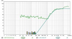
I'm using a 3rd order at 3Khz which yields a 4th order acoustic at 3Khz. I'm using it in a two way with an SB17CAC35 mid woofer which has some extreme breakup which becomes more and more of a problem the higher I move the crossover point. I do have the .01mH inductor in series with the tweeter, I can't decide if it improves the sound or not, it seems a to take a little detail away when I switch it in and out. It is all above my hearing range but my dog can hear it, but she doesn't care enough to give me her opinion.I was going to edit and ran into the time limit.
To be honest and fair the ribbon is a lovely thing, but anything sub 2500Hz needs cutting sharply. 3kHz 4th order is more close to reality than the datasheet recommended circuit.
It is even better crossed slightly higher, 3.5 to 4kHz.
The rise between 10k and Ultrasonic-ville, can be easily dealt with using a single series coil of (if I recall from way back when....) something like 0.1 mH.
I'll have to run the file in Boxsim2 and refresh my memory!
I think you should be careful here.I'm using a 3rd order at 3Khz which yields a 4th order acoustic at 3Khz. I'm using it in a two way with an SB17CAC35 mid woofer which has some extreme breakup which becomes more and more of a problem the higher I move the crossover point. I do have the .01mH inductor in series with the tweeter, I can't decide if it improves the sound or not, it seems a to take a little detail away when I switch it in and out. It is all above my hearing range but my dog can hear it, but she doesn't care enough to give me her opinion.
3rd order electrical is not going to equal 4th order acoustic response.
Reason: there is useful output way below 2kHz, at least the "H" version (also some people make .frd with a high pass that impinges upon the bandwidth, others not.)
So you really need the electrical slope of 4th order at 3kHz or a higher XO point.
Naturally that stretches the midrange.
The Visaton AL130 has a breakup peak about 7kHz, which limits its useful range to about 2.5kHz at the most.
This is a driver I wanted to be able to use with the fountek, since the mids are butter smooth; but it isn't practical, without exposing the 5"er breakup (which I'd worked hard to nuke as far as possible)
With a 4" mid, smooth to about 8kHz, different story; loads of room for a sensible 4k crossover, that both drivers will like.
Interesting, I am measuring it and it does show a 4th order slope. I'm using it in a two way so 4Khz isn't an option, I have used it's little brother in a a 3way and I crossed it to a 4" mid at 4500hz. I will keep trying and if it just doesn't work I will have to switch to a dome tweeter.I think you should be careful here.
3rd order electrical is not going to equal 4th order acoustic response.
Reason: there is useful output way below 2kHz, at least the "H" version (also some people make .frd with a high pass that impinges upon the bandwidth, others not.)
So you really need the electrical slope of 4th order at 3kHz or a higher XO point.
Naturally that stretches the midrange.
The Visaton AL130 has a breakup peak about 7kHz, which limits its useful range to about 2.5kHz at the most.
This is a driver I wanted to be able to use with the fountek, since the mids are butter smooth; but it isn't practical, without exposing the 5"er breakup (which I'd worked hard to nuke as far as possible)
With a 4" mid, smooth to about 8kHz, different story; loads of room for a sensible 4k crossover, that both drivers will like.
- Home
- Loudspeakers
- Multi-Way
- Need advice on dealing with a Fountek NeoCD3.0 tweeter