Show me the Zobel network in any valve amplifier? That's right, they are not used!
Ready to eat that hat?
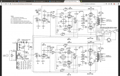
http://www.mcshanedesign.net/CitIIsch.jpg
Attachments
Zobel network for an amplifier that uses a transformer coupling to the loudspeaker? Whatever for??
It will have no consequence. Valve amplifiers have never used them and have never needed them.
To add one seems a bit silly. If they were needed, I would have thought, they would have been fitted before,
in over 80years of valve design and use.
The Luxman MB3045 did indeed have a Zobel at the output.
They even recommended replacing the small 10 Ohm resistor with a higher power one when bench testing.
The examples shown are to modify the negative feed back and stop issues with poor quality transformers. Zobel networks work only to ensure the load on a solid state amplifier stays the same over the higher frequency range. If one remove the Zobel network and then loads the amplifier with a piezo horn, as an example, the amplifier will take off.
Snake oil!
Just realise that I cannot cut beacause is multi-layer PCB.
I could put 2K..60K stopper resistor between the DC-block capacitor (220n) and the grid capacitor (470K), so soldering to one floating leg of the capacitor to the PCB. Which value do you reccomend for EL34/KT66 ?
A resistor in the range 2.2 kohm to 6.8 kohm is normal for EL34. A little higher for KT66.
Note that the gm for an EL34 is almost twice that of a KT66. Hence unless the amp was specifically designed to work with both, you can expect problems. If it was designed and tested for KT66 and you put in EL34, that would likely cause oscillation.
Is this an ultra-linear amp? Poorly designed output transformers can cause oscillation, though it will usually be merely supersonic and not HF. So it won't be affected by small load capacitors like 220 nF.
IMPORTANT: The grid stopper resistor MUST be installed close to the grid pin. If there is an inch or so of PCB track between them it may not do the job.
Weirder and weirder! Who the heck decided on a multilayer PCB for tube amp? Why? What a waste of money!
Last edited:
The examples shown are to modify the negative feed back and stop issues with poor quality transformers. Zobel networks work only to ensure the load on a solid state amplifier stays the same over the higher frequency range. If one remove the Zobel network and then loads the amplifier with a piezo horn, as an example, the amplifier will take off.
Snake oil!
Actually the transformers in the Citation II are pretty highly regarded and the amplifier is fairly wide band by the standards of the day. Other examples of some fairly highly regarded designs have also been provided, the common thread is that they tend to have high feedback margins and extended bandwidth compared to some other designs. I envy your assurance and expertise as exhibited on countless threads across the forum, I wish I possessed just a small % of the knowledge you so adeptly marshal on an almost impossibly diverse range of subjects.
The examples shown are to modify the negative feed back and stop issues with poor quality transformers. Zobel networks work only to ensure the load on a solid state amplifier stays the same over the higher frequency range. If one remove the Zobel network and then loads the amplifier with a piezo horn, as an example, the amplifier will take off.
Snake oil!
I don't have circuits for the Heathkit amps cited, but the circuits posted by Kevinkr clearly show classic zobels in parallel with the output. These are C13 & R34 and C29 & R69 in the Citation II. In the Harmon-Kardon, the designations are too small to read, but zobel CR networks are cleary across the speaker terminals. In neither case are these CR networks in the feedback circuit and are in the wrong place to compensate for transformer limitations. - however zobel networks, by straightening out the speaker impedance, assist the feedback as I said before.
I love your second sentence, John. It is a classic case of someone who ealier said "they are of no use" [your post #16] who is beginning to see that a) he's wrong and b) he has no idea what he is talking about, reflecting back what was said by others and trying to change his story. And you have admitted CR networks across the output do indeed do something useful.
Hmmm. I've just remembered. You are the bloke who claims 50 years experience and had never heard of Ducon.
Last edited:
Ok solved.
I put a real Zobel calculated network at the input of my fullrange 16 ohm loudspeakers.
It seems they (or the amp) really needed it!
R=15ohm
C=0.68uF
That works the best.
I have tested the same at the close output of the amp, but it reduces a bit the soundstage. So I put after power wiring. I did't test to move it ahead on the primary.
Stopper resistor would be at least 2-3 inches far from the tube, so I did't put, also because I don't think now (by ear) to need it.
Why moved back from 0.22uF to 0.68uF ?: I made another (you will say dangerous, I know, I know...) improvement: floating outputs!
The ampli doesn't have any global NFB, and the L&R minus taps were connected toghether to the chassis, connected to the ground.
I removed the grounding from the minus taps of the output to the chasiss and I have also cut the link between the two L&R minus taps: much more clean mid-high now.
(By the way I don't think this it is so much dangerous: being now floating, (read "isolated"), it would be nearly impossible for the transformer to arc between primary and secondary, or at least the cases are really reduced)
It is not unsafe now, it may become unsafe later.
The reason why floating transformer outputs are considered dangerous is this: Should a primary-secondary short circuit occur, there will be no symptoms. The amp will continue to operate. Later, should you decide to alter the speaker wiring, or a child touches the speaker terminals, they will contact high voltage. The probability of such a fault may be very low, but the consequences may be very serious.
Arcs aren't the only way shorts can occur. In any case, while you may think a floating secondary removes the possibility of voltage stress, you would be wrong, because at volume sufficient for clipping, the primary sees not just the HT, it sees AC peaking at up to twice the HT rail, and the secondary can only see 1/20th of this.
If the secondary minus wires are earthed, any short in the transformers will stop the amp from working, and you will know immediately that there is a fault. And neither you nor any child fooling around can get a shock.
A good engineer tries as much as possible to design circuits so that realistic failure of any part results in obvious symptoms and presents no safety hazard.
Having said that, it is not dangerous to have floating transformer secondaries provided the transformer insulation and construction is appropriate. As is done with power transformers in double insulated appliances. Tube output transformers are not USUALLY designed to permit floating secondaries, but they can be.
Who designed the PCB?
Last edited:
Who designed the PCB?
Here:
http://www.diyaudio.com/forums/tube...er-5z4p-rectifier-review-mod.html#post4180566
I'm told (and have seen it written in many books) that tube/valve power amplifiers must have the load connected at all times that the amps are ON.
Is this to do with the amp seeing a "design load" at all times?
What happens when the load is disconnected?
Does the tube/valve amp oscillate?
Could we do something to make the tube/valve amplifier tolerate a disconnected load?
Would a primary winding located Zobel meet this function?
O at least make it more tolerant of a "too high" load impedance?
... tube/valve power amplifiers must have the load connected at all times that the amps are ON.
Is this to do with the amp seeing a "design load" at all times?
What happens when the load is disconnected?
If the load is disconnected, the 'load line' for the output valve(s) becomes almost horizontal. This creates very a high anode voltage swing (much higher than the HT) and can cause flash-over at the valve pins or insulation breakdown in the output transformer.
I think the impedance of the Zobel network would be too high at low frequencies to help much.
1. What happens when the load is disconnected?
2. Does the tube/valve amp oscillate?
3. Could we do something to make the tube/valve amplifier tolerate a disconnected load?
4. Would a primary winding located Zobel meet this function?
O at least make it more tolerant of a "too high" load impedance?
Answers as numbered:-
1. The output transformer becomes a high-Q inductance. This measn that if any signal causes tube cutoff, there will be a back-emf arising in the transformer, which may be several kilovolts. This will cause destruction of the transformer insulation, internal arcing in the output tube(s) and therefore damage to tubes, of if you are lucky, merely arcing between the pins on the tube socket.
2. Not inherently. However, the overal voltage gain will rise dramatically and this MAY cause oscillation, even if neg feedback isn't used, due to grid-anode and wiring stray capacitance. If oscillation occurs, often the amp is rapidly destroyed.
3. Yes. There are several methods: a) use negative feedback. A few dB Feedback by means of a resistor from output anode to driver anode is particularly effective. You must ensure that the amp is stable without load, otherwise global feedback can make things worse - see Ans (2). b) shunt resistors acroos the transformer primary. This causes power loss, but has for instance been used in low cost RCA amplifiers. c) clamp diodes. Clamp diodes were never used in commercial products when tubes were king, due to the cost, but it is a valid method. Be carefull about using semiconductor diodes. Regular high voltage power diodes aren't fast enough; d) small anode/screen grid CR series networks in conjuction with ultralinear mode, octal socket tubes, and generous transformer insulation.
4. Essentially no - the capacitance is way too small. However with ultralinear, only the transformer leakage reactance is a problem, confining the spikes to high frequencies and the small capacitance of a zobel network may be sufficient - see (d) in Ans (3) above.
In professional grade equipment eg that used in radio stations, it was normal to use the methods discused in (3) and test the prototype to ensure the amp could indeed tolerate an open load.
Last edited:
Zobel network is at the output of all solid state amplifiers. Solid state amplifiers are only stable with a perfect Resistive load that has no capacitive reactance. Anything that causes a slight high frequency rotation of phase at the amplifier output is fed back through the negative feedback path to the -inverting input. The comparator can only function correctly if the phase is exactly correct across all frequencies. If not, the negative feedback becomes positive feedback causing the amplifier to oscillate.
Zobel network design is based on transmission line theory. All wires including printed circuit tracks have specific lengths that randomly co-inside with fractional numbers of Rf (radio frequencies) wavelengths. This can cause slight rotational phase shifts typically between 50kHz to 1Mhz. The Zobel network represents a phase correcting load across the amplifier's output. It attempts to keep the combined small capacitive effects of the amplifiers printed circuit tracks, internal wiring to the speaker terminals, and the speaker cable appearing as a phase coherent resistive load. Only a very few professional amplifier designs have achieved excellent performance stability under most load conditions.
 Similar to marriage and helicopters there is no such thing as a naturally stable solid state amplifier. All solid state amplifiers are parasitically unstable once a speaker cable is connected, its only a matter of degree. Cables of differing lengths and styles can cause bursts of parasitic oscillation to randomly appear on different parts of an audio waveform. Changing cable may stop or shift the parasitic to different positions. Parasitic sub-harmonics can be heard within the music.
There is un-intentional incorrect information on Zobel networks on many web sites. A Zobel network in an amplifier does not provide correction for impedance variation of a speaker. Some passive crossovers include a correcting network for impedance variation of a speaker inside the speaker box also described as a Zobel, but it is not the same Zobel as in the amp.
Source The Lenard Institure.
Zobel network design is based on transmission line theory. All wires including printed circuit tracks have specific lengths that randomly co-inside with fractional numbers of Rf (radio frequencies) wavelengths. This can cause slight rotational phase shifts typically between 50kHz to 1Mhz. The Zobel network represents a phase correcting load across the amplifier's output. It attempts to keep the combined small capacitive effects of the amplifiers printed circuit tracks, internal wiring to the speaker terminals, and the speaker cable appearing as a phase coherent resistive load. Only a very few professional amplifier designs have achieved excellent performance stability under most load conditions.
There is un-intentional incorrect information on Zobel networks on many web sites. A Zobel network in an amplifier does not provide correction for impedance variation of a speaker. Some passive crossovers include a correcting network for impedance variation of a speaker inside the speaker box also described as a Zobel, but it is not the same Zobel as in the amp.
Source The Lenard Institure.
Last edited:
Zobel network is at the output of all solid state amplifiers......
John, give it away. You have no idea what you are talking about. Just about everything you said is wrong - demonstrably wrong.
Nobody will think ill of you for making one erroneous post. We all make mistakes. But if you keep trying to defend the indefensible, you just look stupid.
Soilid state amps are not necessarily unstable without a zobel network. There IS such a thing as a naturally stable SS amplifier - one with no neg feedback for start. In fact, apart from the very earliest ss amp where economics made design engineers make do with power transistors with cutoff frequencies in the kHz region, SS amps are MORE stable as there is no output transformer, and there is DC coupling. It's very widely known that SS can have vanishingly low THD from using neg feedback much larger than was common with tube amps because of the better stability.
Vast numbers of SS stereos and radios have been churned out of factories without any zobel networks. Including equipment of very high quality. Just as with tube amplifiers, some designers include them and some don't.
Zobel network design is most certainly NOT based on transmission line theory. A correctly designed zobel network is merely the conjugate impedance of the loudspeaker, modeled as an inductance in series with a resistance. The L//R part in series as shown in your diagram is an added dodge to isolate the amp from any undefined behaviour of the speaker and cabling above the audio range.
Your comment "only a few professional amplifier designs have achieved excellent stability..." is patently obviously wrong. As an example, the 7W to 10W designs published by Philips and Mullard applications labs in the 1960's to help sell their AD161/2 germanium power transistors are completely stable on any load within ratings - and they have no zobel network either. I have a 1967 HMV solid state stereo - it's completely stable too. THD below onset of clipping is below about 0.2% - very good for its' day.
However you are correct in saying some loudspeaker systems have internal zobel compensating networks.
Last edited:
The examples shown are to modify the negative feed back and stop issues with poor quality transformers.
Besides the Citation amps (with superb transformers) and the Luxmans (ditto), have a look at the Marantz 5, 8, 8B, and 9. All with top quality iron, some of the most highly regarded tube amps ever made. Oh yes, also all of the classic McIntosh tube amps.
At a certain point, it's wise to say, "I was totally wrong and I appreciate everyone's input to correct me."
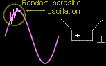
There is another use of Zobel networks and that is to compensate for instability in a circuit which results not in a constant oscillation,but rather snivets. I've seen this with some sweep tubes
It can be argued that a proper design (and LAYOUT) will not have them, however I've seen them in breadboarding such as my 6P41S UL SE amp. The problem is most likely layout as the amp which is on a 2' X 2' breadboard with flying leads all over the place.
With this amp, I will use them across the transformer primary even in the final build just to be certain they (snivets) don't occur. The zobel capacitor is calculated from the frequency of oscillation and the measured leakage inductance of the output transformer.
For those interested, look up SMPS snubber (more common reference to an RC series network than Zobel, at least in my field ).
Zobels are commonly used in SMPS to suppress ringing on the transformer and I've used the recommended method from those articles to calculate values for my zobel.
I'm doing my prototyping with the speakers I expect the amp to be used with, however there is no guarantee that some time in the far future, my daughter and SIL might buy another set of speakers when I'm not around and I want to be confident that the amp wont' have problems.
Taking your statements one at a time:JonSnell Electronic said:Zobel network is at the output of all solid state amplifiers. Solid state amplifiers are only stable with a perfect Resistive load that has no capacitive reactance. Anything that causes a slight high frequency rotation of phase at the amplifier output is fed back through the negative feedback path to the -inverting input. The comparator can only function correctly if the phase is exactly correct across all frequencies.
Zobel network design is based on transmission line theory.
No - although many SS amps do include a Zobel network.
No - although the wrong amount of capacitive reactance can cause stability problems for many amps or any other device (such as a follower) with heavy negative feedback.
Yes - obviously any phase shift at the output will be fed back to the input via the feedback loop.
No - the input subtractor (not comparator) does not require exactly correct phase, just phase which is not too far out. 'Not too far out' generally means within about 90 degrees of pure negative, although clever design can go further.
Not really - at least not in the way you probably mean. You could regard a Zobel network as a piece of lumped lossy transmission line, but you can also regard it as a lossy diplexer. It has nothing to do with PCB tracks as transmission lines.
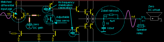
The Zobel network in a typical SS amp has two related functions:
1. It stops the output stage (typically some form of follower) from seeing a low-loss capacitive load at HF, so preventing local parasitic oscillation.
2. It stops the global feedback loop from gaining too much HF phase shift with a capacitive load, so preventing global loop oscillation.
Note that a Zobel network does not prevent a capacitive load; it actually provides a partly capacitive load at low HF frequencies, but a more resistive load at higher HF where the problems might occur.
sorry to resurrect this 5 year old thread, but i am looking for information on whether an rc snubber network across the OPT of the tube amp been done before? thoughts?
- Home
- Amplifiers
- Tubes / Valves
- Need a Zobel Network (or RC shunt) in tube amplifier?