Hey DIYers -
Tackling a Pioneer SA-700 - needed a little love after a long time and one of the channels was blown from who knows what .
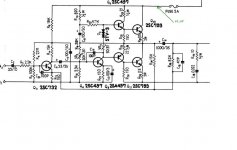
Replaced a few things - but the issues seem to be appearing in the main amp circuit (W15-60 in the schematics).
Unfortunately when powered up we got a pop and smoke. I was able to isolate the issue (smoking gun) to R24 and R27. And I discovered I had erroneously slotted in the transistors when replacing them (swapped base with collector.) Removed the resistor and tested (still getting reading within value) though the Transistor didnt survive.
Replaced the Transistor in question (Q6, only tackling one side at the moment) - correctly this time and tested the remaining transistors along with the larger output transistors on the heatsink. It all checks out.
Amp powers up, no smells, no odd sounds, but the channel is dead.
Long story short is - could all of the eletrolytics on that side have blown as well? Short of testing every resistor - I dont have anything else to test - wiring is good and incoming voltage to the board checks out.
Any one have some suggestions? To be clear the amp was functioning before, properly, if poorly.
Happy new year , and thanks to everyone!
Tackling a Pioneer SA-700 - needed a little love after a long time and one of the channels was blown from who knows what .
Replaced a few things - but the issues seem to be appearing in the main amp circuit (W15-60 in the schematics).
Unfortunately when powered up we got a pop and smoke. I was able to isolate the issue (smoking gun) to R24 and R27. And I discovered I had erroneously slotted in the transistors when replacing them (swapped base with collector.) Removed the resistor and tested (still getting reading within value) though the Transistor didnt survive.
Replaced the Transistor in question (Q6, only tackling one side at the moment) - correctly this time and tested the remaining transistors along with the larger output transistors on the heatsink. It all checks out.
Amp powers up, no smells, no odd sounds, but the channel is dead.
Long story short is - could all of the eletrolytics on that side have blown as well? Short of testing every resistor - I dont have anything else to test - wiring is good and incoming voltage to the board checks out.
Any one have some suggestions? To be clear the amp was functioning before, properly, if poorly.
Happy new year , and thanks to everyone!
Q.......- but the issues seem to be appearing in the main amp circuit (W15-60 in the schematics).
What schematic?
-------
Does this mean, there is a signal at the output transistors? (is there a relais behind the output transistors,.......and some switches for the speakers?)
What schematic?
-------
Does this mean, there is a signal at the output transistors? (is there a relais behind the output transistors,.......and some switches for the speakers?)
I meant the amp schematics - Pioneer SA-700 Manual - Solid State Stereo Amplifier - HiFi Engine
W15-060 refers to the Main Amp board/scheme.
I am getting two different readings at the output transistors -
Q12
B - 0
E - 0
C - 22.4V - though the reading is steadily increasing - last I checked it was 23.4V and climbing - I turned it off to avoid any damage or the unknown.
Q10
B - 23.8V
E - 24.1V
C - 65.6V
As far as the switches for the speaker - its a rotary switch that also serves as the power knob. OFF - A - NO SPKRS - HEAD - B - A+B
There are only two resistors there and they test fine - amp is working formidably in the separated "pre" function - unrelated but anyways.
Thanks again for the help
Build a 'lamp tester' and plug your amp into it.
You then have unlimited time to diagnose any faults with much less chance of blowing stuff up.
Dan.
You then have unlimited time to diagnose any faults with much less chance of blowing stuff up.
Dan.
Tip - disconnect B & C of output transistors (or remove them).
This amplifier will still function for diagnosing process.
Dan.
This amplifier will still function for diagnosing process.
Dan.
Hi,
I am doing the same repair job for SA-700.
What are the purposes of VR1(VR2) and VR3(VR4)?
For setting the bias or...?
Reading thru' the service manual there is still no hint.
Any advice?
Thanks in advance.

I am doing the same repair job for SA-700.
What are the purposes of VR1(VR2) and VR3(VR4)?
For setting the bias or...?
Reading thru' the service manual there is still no hint.
Any advice?
Thanks in advance.
vr3/vr4 ......bias current
vr1/vr2 .....operating voltage at the output (at c13/c14 + pole, should be around half power supply voltage)
vr1/vr2 .....operating voltage at the output (at c13/c14 + pole, should be around half power supply voltage)
Last edited:
To be more precise, VR1/2 are usually adjusted for symmetrical clipping under load.
When there are issues with the output stage blowing up, check VR3/4 for bad contact and D1/2 for intermittency. If in doubt, use a bulb tester. If it lights up now and then, use a chain of 3 small-signal diodes in parallel with D1/2.
BTW, 100µ/3V caps? 1980s-vintage 4 V caps were bad enough.
Speaking of those, check leakage current / voltage handling on the output coupling caps. 1000µ is a bit small even for 8 ohm loads, btw.
- Status
- Not open for further replies.
- Home
- Amplifiers
- Solid State
- Need a quick hand with a Pioneer SA-700