Hi
A few years ago I got a tremendous amount of help from Several members when changing from Seas Magnesium drivers to Nextel drivers due to corrosion. The Cabinets were the small thor and with the great help of this community I was able to get very good results. When I started on the DIY thing I was sceptical and built really fast boxes which I never finished and which were really not very well done so fast forward 13 years and I am building a pair of speakers with the same drivers and crossovers. Using a holey braces from the old Thor but I wanted to move them into the main area of the house from the basement so I am making extra small thor speakers. The speaker will be 43 x 8.75 x 12 or internal dim of 7 1/4 (183)x 10 3/8 (264) 42 (1070) the tweeter is 31 1/4 (795) from the internal base.
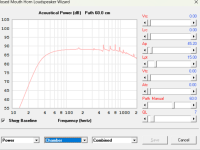
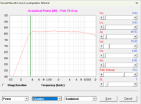
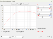
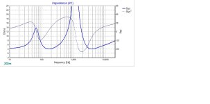
My intention is to build a BR speaker I would have prefered a mltl but after spending many many hours on Hornresp I have come to the conclusion that I am not familiar enough with speaker building to get this right. So my question is when I do put the numbers in at 43 liters and 107 length I end up with the attached chart

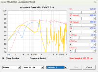
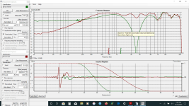
As I understand it the path is the distance for the center of the tweeter to the center of the port. So setting the path at 70cm I get

I really like the way the small thor sounded. So I would like to replicate as much as possible given the limitation on the size of the speaker and the nextel drivers.
So my questions are if built as a BR speaker will fiber fill take care of the jagged peaks and valleys?
Where is the best place to put the port?
To Run hornresp as a TL - With the holey braces in how do I calculate the S1 S2 S3 ?
Where does the horn start do I measure from the tweeter (mtm) to the top of the box and back down to the bottom?
What effect does the vertical holey brace have? is it a divider or just a brace is my horn length 107 or 142 or 249 ?
I very much appreciate Hornresp and thank you David for creating it.
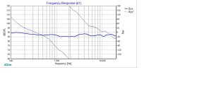
Here is the listening position FR for the small thors with the nextel drivers after much help from Allen and Lojzek GM and many others they are now in the campfire and the braces are in the new speakers

A few years ago I got a tremendous amount of help from Several members when changing from Seas Magnesium drivers to Nextel drivers due to corrosion. The Cabinets were the small thor and with the great help of this community I was able to get very good results. When I started on the DIY thing I was sceptical and built really fast boxes which I never finished and which were really not very well done so fast forward 13 years and I am building a pair of speakers with the same drivers and crossovers. Using a holey braces from the old Thor but I wanted to move them into the main area of the house from the basement so I am making extra small thor speakers. The speaker will be 43 x 8.75 x 12 or internal dim of 7 1/4 (183)x 10 3/8 (264) 42 (1070) the tweeter is 31 1/4 (795) from the internal base.
My intention is to build a BR speaker I would have prefered a mltl but after spending many many hours on Hornresp I have come to the conclusion that I am not familiar enough with speaker building to get this right. So my question is when I do put the numbers in at 43 liters and 107 length I end up with the attached chart
As I understand it the path is the distance for the center of the tweeter to the center of the port. So setting the path at 70cm I get
I really like the way the small thor sounded. So I would like to replicate as much as possible given the limitation on the size of the speaker and the nextel drivers.
So my questions are if built as a BR speaker will fiber fill take care of the jagged peaks and valleys?
Where is the best place to put the port?
To Run hornresp as a TL - With the holey braces in how do I calculate the S1 S2 S3 ?
Where does the horn start do I measure from the tweeter (mtm) to the top of the box and back down to the bottom?
What effect does the vertical holey brace have? is it a divider or just a brace is my horn length 107 or 142 or 249 ?
I very much appreciate Hornresp and thank you David for creating it.
Here is the listening position FR for the small thors with the nextel drivers after much help from Allen and Lojzek GM and many others they are now in the campfire and the braces are in the new speakers
Center of woofer to port.path is the distance for the center of the tweeter to the center of the port.
yes, probably. You could still try to simulate an offset port mass loaded transmission line and see what filling will do.will fiber fill take care of the jagged peaks and valleys?
Have a look here, bass reflex and mass loaded TL:
https://www.diyaudio.com/community/...rbers-and-port-geometries.388264/post-7695049
And the MLTL hornresp record:
https://www.diyaudio.com/community/...rbers-and-port-geometries.388264/post-7696655
Avoid pressure peaks of the longitudinal resonances. Best simulate without filling using hornresp, reduce lower frequency peaks by adjusting driver and port position and then add filling at the TL ends to even out the high frequency wiggles.Where is the best place to put the port?
By the way, your tuning seems a bit high, leading to a resonance peak at tuning frequency. Mayby increase the volume? Or increase port length.
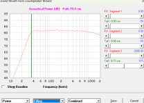
thank you I am using the tweeter because it is an mtm. using double the sd - I do not understand how to calculate s1 I get the following chart Does this mean I need to add a pound of fiber fill to the top of the chamber? to minimize the resonance? thank you

switch to the "schematic" view in the loudspeaker wizard to see how the sliders change the filling and it's graphic representation.Does this mean I need to add a pound of fiber fill to the top of the chamber?
also note that your wizard seems to indicate a traditional transmission line, not an offset port mass loaded TL, if I am not mistaken!
the offset port MLTL is essentially a bass reflex box with a long enclosure that allows you to simulate the longitudinal resonance.
the advantage of an offset port mass loaded TL is: much less length required and a very good possibility to cancel all unwanted resonances.
the disadvantage is a slightly reduced main resonance output.
How do I find that I looked thru the help and menus and I do not see offset port mltl. I would like to see as the boxes are built and I am painting them. I can add material to make the box smaller and add material to decrease the volume and the location and size of the port but that is about it. when I run the loudspeaker wizard I get a wild power graph.
How do I find that
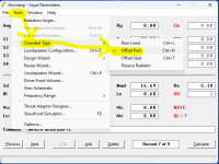
in the loudspeaker wizard you can adjust the port under the "chamber" settings.
the Transmission Line Wizard is not available for mass loaded TL, by the way!
EDIT:
alternatively if you start with the input wizard (under "help") you can chose "offset port" in the transmission line input sequence.
EDIT 2:
I think you will only find the options as shown in my screen shot when there is already a port defined... but input wizard is probably the best method, anyway!
Last edited:
The Help file includes some explanation of of the modelling inputs and outputs such as for S1, S2...To Run hornresp as a TL - With the holey braces in how do I calculate the S1 S2 S3 ?
If using Hornresp, I find the Design Wizard useful in understanding how a speaker driver will interact in the closed, box, bass reflex and TL and default options are provided. From there, user adjustments can be made to see what gains are possible or for other options, the Input Wizard is useful. Dave in the full range forum and others eg GM have over the years posted on their advice for bracing such as positioning etc for maximum effect. A search could chase that down.
thank you this is not getting any better masked is not really an improvement maybe I should burn the boxes before I put the drivers in

If you want just post your hornresp record and get some suggestions?maybe I should burn
I guess the dimensions are fixed but driver and port positions may change?
thank you well its worse than that the drivers are fixed as well the boxes are built but I have not put the ports in yet. here is the input screen I assume the s1 s2 and s3 are the area of the inside of the box. I am confused. as a ported enclosure the graphs look ok with many small spikes but as a TL it looks really bad. I can of course add to the box to make it smaller volume and to some degree make it shorter. is Vrc the total speaker volume and Lrc the total length? I used the holey brace from Dave and Scott in both direction so at 6 1/4" from the front baffle there is a 3/4" vertical brace that has many holes in it. about 1/2 of the cabinet has a brace from the drivers to the back of the cabinet. I am hoping that I am just inputting something grossly incorrect. thank you again

We may have found the issue:is Vrc the total speaker volume and Lrc the total length?
If you input the "horn" dimensions (S1-S4 and lengths of the Con horn sections, defining your speaker enclosure) and a rear chamber (Vrc+Lrc) you essentially build a 4th order bandpass. So you should just set both Vrc and Lrc to 0 (zero).
The enclosure volume is calculated using S1-S4 and L12-L34. The total volume is shown in the "schematic" view.
But you still adjust the port in the "chamber" settings.
EDIT:
By adjusting the L23 slider you change the port position.
have a look at the "schematic" view to see the change.
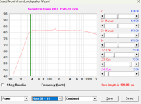
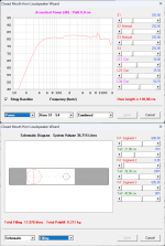
attached a quick proposal with changed port position by adjusting L23 and a filling suggestion.
adding further filling may even out the remaining peaks and dips (but also reduce the bass output slightly).
By the way, because you have two drivers at different positions the peaks and dips will probably be less severe than shown in the hornresp simulation!
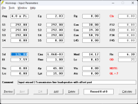
and the respective input mask:
Last edited:
thank you stv that helps me alot I was very unsure about the vrc and lrc that makes me feel much better. I have been working on it for some time and I appreciate your help on it. They should sound good I have a few more coats of paint to put on and then I can start to measure them. thank you again I will update as I make progress. The hornresp program is really something an amazing work of science.
So according to these charts it looks like pretty good power line. I will post once I finish the speaker and start testing. It looks like output 2 is making most of the issues is this the port? and is there a fix? when I run in bass reflex instead of TL the port (i think) still has a negative impact.
Attachments
Yes!It looks like output 2 is making most of the issues is this the port?
Yes and no: the 180 Hz peak is caused by the enclosure length and could be reduced by changing the driver location. But I think that is not possible anymore, right?and is there a fix?
The other higher resonances are caused by further enclosure dimensions and by port length. (Partially) filling the enclosure or just lining the walls will reduce those peaks.
For further information on those peaks have a look at my port resonance thread!
Yes.when I run in bass reflex instead of TL the port (i think) still has a negative impact.
Directing the port to the rear side of the speaker will help.
You could also use passive radiators to reduce resonance peaks.
But don't be too concerned about them. It's common with all bass reflex speakers.
Thank you that helps
because of the mtm -- the tweeter at ear height somewhat limited on the driver location but I should have waited. I got pretty frustrated with Hornresp learning curve it is a great program now that I am starting to understand it but I had a window of time to build the speakers so I went for it. I was thinking that it would not matter much in BR speaker. then I started thinking of the unintended consequence of creating a TL. Just not playing with hornresp the guess location for the drivers was probably the close to the best place to put the driver other locations make the resonance at 180 larger.
The port is not installed and I can put on the back or front. The speaker has holey cross braces side to side from top to bottom and from front to back from the top to about 1/2 way down .I can still get lining in most of the speaker and the back is not attached so I can get stuffing everywhere as needed. The ports have been ordered but not received yet. I still have some reading to do on the ports. Using Hornresp I have the best results for location. I did order 3" ports and it looks like I should wrap them with foam I also bought some wool and have the polyfill from the Thors.
The port threads aret interesting I am uncertain where to put it but using hornresp the best locations are around 70cm from the port 60 can minimize the 180hz peak but 70 improves the 500 to 1000 hz area . I will damp the port with fiber fill material
Would I be crazy to try a sealed cabinet I am waiting for the ports which will be a while in coming and never considered a closed system. I think once the speakers are painted and assembled I may try it before I cut the hole for the ports. Not sure if the crossover will work at it is the original thor crossover with the tweeter cap and resistor removed to match the increased db of the nextels over the magnesium drivers. the last screen shot is with the tweeter inverted to show the actual crossover freq. which matches Joe's.
Attachments
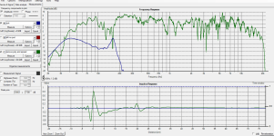
here is the first results I have a suckout between 100 and 200 spreading the wool out helped a little measurements are outside. any thoughts on how to raise the suckout?
thank you
thank you
Attachments
Last edited:
did you do nearfield measurements? otherwise it might just be the room.suckout between 100 and 200
There is a strong longitudinal resonance that exits the port at around 150 Hz (also visible in your hornresp simulation in post #15).
If filling both ends of the enclosure and moving the port position does not help (try with the hornresp simulation) you might consider an internal helmholtz absorber: see here (also find a link to a german in depth description - eventually use a translator).
installing such an absorber might need some tweaking, but once it's installed it works very well!
- Home
- Loudspeakers
- Multi-Way
- Need a little help with a speaker build
