Anyone have a simple test circuit?
I have a bunch of BC556B (pnp) and want to select them for an LTP stage.
I have a bunch of BC556B (pnp) and want to select them for an LTP stage.
I don't bother with matching, the difference is so little its in the region of 0.0001% THD difference or less in matched or unmatched.
Tekko,
You need to match the transistors to minimize the offset voltage. Yes, unmatched device will produce very little distortion in a closed loop amp, but that's not the reason for matching.
Rick
You need to match the transistors to minimize the offset voltage. Yes, unmatched device will produce very little distortion in a closed loop amp, but that's not the reason for matching.
Rick
That is matching for Hfe, he asked for a circuit to measure noise. I assume he wants the 'quietest' specimens for his LTP.
Even offset difference will be so small that matching is a waste of time, atleast in a hobby project.
However if it was a commercial product like a high precision instrumentation amplifier, then matching is highest priority.
However if it was a commercial product like a high precision instrumentation amplifier, then matching is highest priority.
Even offset difference will be so small that matching is a waste of time, atleast in a hobby project.
I tend to agree. The 'correct' way is to match them though. I haven't and didn't have any significant output offset.
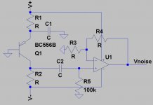
RJM1, how do i work out the component values for a +/-12v supply and 1ma thro Q1?
what R values for the opamp?
use a scope on the output?
thanks.
what R values for the opamp?
use a scope on the output?
thanks.
I really appeciate the idea. In the short time that I am readig this forum, I have seen that much concern is taken for THD, then less for offset, but very few for noise. If I remember well the noise should be indeed of concern specially with FET transistors that should (correct me if I am wrong) be affected of 1/f noise. Also I never have seen explicitely (maybe it was done anyway) dimensioning resistors for noise avoiding. I mean trading a higher dissipation with a smaller R. This is done always when you design measurement instruments. Sometimes I had also the impression ( i should research on that) that sophisticated schematics (i.e. cascoded and double CCSs, especially Zener ones) besides of the linearity (read THD) advantages may bring in additional noise. Very interesting post
effebi
effebi
R1 = 11K, R2 = 5.6K for 1ma at +-12V, caps about 10uF, R3 about 100, R4 I’d just use a 1M pot and adjust it to a good level since you are just comparing transistors and don’t need to measure actual noise levels. Measure with a scope or a volt meter. Scope is better.
Note that:
* There is voltage and current noise. You want to test for both unless you're sure one is negligible for your application.
* To measure noise you want a well-defined bandwidth which is meaningful for your application (e.g. 20 kHz for audio). In other words: you need a low-pass filter somewhere.
Samuel
- Status
- Not open for further replies.
- Home
- Amplifiers
- Solid State
- Need a circuit to noise test BJTs