Hi Folks,
Long time lurker, finally registered. I like to restore vintage equipment, my most recent was a complete recap of a Pioneer SX-1080.
However, in our living room we have a Sony STR-D3070 A/V receiver. It is circa 1991. Rated at 120 watts per channel, I have it driving a set of Bose 601 Series 3's.
Trouble free all these years, but today we powered it up and the right channel burst some static, then exhibited sounds very close to a dirty volume pot. After static stopped, turning it way up on the right side you can hear the music very faintly at full volume. Turned it back down and left it for a minute or two and random bursts of static would happen.
Left channel is fine.
I switched sources and speaker wires back and forth to be sure. The right channel is dead.
I took it apart and applied Deoxit to the volume and balance pots, no change. I took off the bottom plate and used the butt end of my insulated screwdriver to tap and press all over the main board and all the other boards, and I could get no change.
I have a service manual, and noticed there is this STK-3122-3 soldered to the main board. It seems the job of this STK is to run the power amp outputs.
So I took my meter to the 15 leads of the STK-3122-3 and I found something interesting. Here are the results of my readings presented this way:
Pin#
Schematic Value
Reading
Results:
Pin 1
-0.2
-.282
Pin 2
-0.2
-.306
Pin 3
60.9
69.4
Pin 4
60.6
60.2
Pin 5
-1.1
-1.15
Pin 6
1
1.089
Pin 7
61
-61
Pin 8
0.1
-.002
Pin 9
60.9
-61.4
Pin 10
1
1.071
Pin 11
-1.1
-1.111
Pin 12
60.9
60.3
Pin 13
60.9
60.4
Pin 14
-.3
-.322
Pin 15
-.3
-.290
Note I bolded pin 7 and 9.
I have already ordered a replacement STK-3122-3 but I wanted to ask you experienced people your opinion of what might be happening with Pin 7 and 9 and if this is a failure mode? In your experience, does this show a dead STK?
Thanks for any help.
Cheers!
Pin 9 is the positive supply and pin 7 the negative.
So pin 7 measured value looks correct. The marked value is incorrect (happens all the time in old service manuals).
Pin 9 should have PLUS supply present. You measure a negative value which points to a missing supply (fuse or safety resistor open circuit). That doesn't tally with it working on one channel though as the chip is a dual.
Hi Mooly,
Thanks for your reply.
I'll check for a dead fuse.
Just a quick question... would that safety resistor be external?
Your last comment makes me think their is another possible fault in the circuit I should chase or should I replace the STK and see what happens? I ordered two in case I zorched one.
Thanks!
Any safety resistor would be somewhere on the main PCB... external to the STK, yes. STK's of all varieties have been used for years in audio equipment and tbh and as a generalisation, they can fail. We never used to get that heavy in faultfinding, it was always change the STK first. That said, this one is a little different in that this STK is more of a low powered 'front end' rather than the complete amplifier on a chip, which most STK's are.
You need to confirm the supply voltages first though. If they are incorrect and pin 9 really is negative then you need to look for what has failed in the supply first. You might be lucky and find that is all the problem is.
You need to confirm the supply voltages first though. If they are incorrect and pin 9 really is negative then you need to look for what has failed in the supply first. You might be lucky and find that is all the problem is.
Thanks Guys,
Really appreciate you folks taking the time to reply.
Mooly I will tear into this beast a bit more. It's not an easy one to tear down, but I'll give it a whirl.
Cheers!
Really appreciate you folks taking the time to reply.
Mooly I will tear into this beast a bit more. It's not an easy one to tear down, but I'll give it a whirl.
Cheers!
Still at it
Hi Mooly,
Just checking in.
Work performed so far:
- Visual inspection of all boards - no signs of any zorched components
- Rap and pressure test with butt end of insulated screwdriver on all boards to check for cold solder joints found no crackles or intermittent connections anywhere.
- Re-seated all ribbon cables and cleaned all plug and socket type connections.
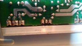
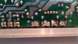
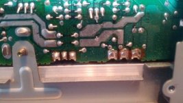
- Close-up inspection of all solder pins on the foil side of the main board - no cold solder joints found
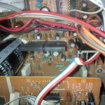
- Photos taken of main board output transistor solder connections for your opinion - attached
- Noted STK-3122 runs very hot, and has no factory installed heat sink. See attached picture of it with just some kind of weird clip.
- All fuses check out OK.
I took delivery of the two replacement STK-3122III chips - see pics. Note - the one in the receiver shows the number 1806 printed on the front right corner. The back has the alphanumeric C3122H3G9D.
The new STK-3122III chip shows PMC D4 on the front right corner, and 3122F5H3 on the back.
If I go ahead and switch it out with this new one, do you think I am safe with this substitution?
Regarding your comment of checking the supply voltages, I want to make sure I am measuring the correct location. Can you have a look at the crop of the schematic to point that out to me? I have the service manual in PDF here I could email you to help me sort that out and where to find that safety resistor.
Here's to hoping you have the time to help me with this project, I understand if you don't. Appreciate the direction so far.
Cheers!
Scott
Hi Mooly,
Just checking in.
Work performed so far:
- Visual inspection of all boards - no signs of any zorched components
- Rap and pressure test with butt end of insulated screwdriver on all boards to check for cold solder joints found no crackles or intermittent connections anywhere.
- Re-seated all ribbon cables and cleaned all plug and socket type connections.
- Close-up inspection of all solder pins on the foil side of the main board - no cold solder joints found
- Photos taken of main board output transistor solder connections for your opinion - attached
- Noted STK-3122 runs very hot, and has no factory installed heat sink. See attached picture of it with just some kind of weird clip.
- All fuses check out OK.
I took delivery of the two replacement STK-3122III chips - see pics. Note - the one in the receiver shows the number 1806 printed on the front right corner. The back has the alphanumeric C3122H3G9D.
The new STK-3122III chip shows PMC D4 on the front right corner, and 3122F5H3 on the back.
If I go ahead and switch it out with this new one, do you think I am safe with this substitution?
Regarding your comment of checking the supply voltages, I want to make sure I am measuring the correct location. Can you have a look at the crop of the schematic to point that out to me? I have the service manual in PDF here I could email you to help me sort that out and where to find that safety resistor.
Here's to hoping you have the time to help me with this project, I understand if you don't. Appreciate the direction so far.
Cheers!
Scott
Attachments

One more measurement
Using my multimeter set at 2V and with no speakers connected, with the receiver on FM and volume at 0, I measured the speaker outputs:
Right ( the dead channel ) is alternating between -.021 and -.022
Left is -.023 steady
Cheers!
Using my multimeter set at 2V and with no speakers connected, with the receiver on FM and volume at 0, I measured the speaker outputs:
Right ( the dead channel ) is alternating between -.021 and -.022
Left is -.023 steady
Cheers!
The different numbers sound like production codes... no problem. As long as its an STK-3122III it should be OK.
All the resistors with exclamation marks are safety resistors but the two we are immediately interested in are those to pin 9 and pin 7. You should have PLUS 60 volts or so on both ends of R787 and MINUS 60 on both ends of R737.
I think that is where we left off... and they are the first things to check.
To measure the speaker output voltage you need to be checking this before the relay, so that is on the line L751 and L701 connect to.
If the safety resistor to the STK is open circuit then you need to confirm there are no other obvious issues such as failed output transistors and that the 0.1 ohms that connect to the output transistors are OK. You then have the option of trying a new resistor (more in hope) or perhaps simply replacing the STK and the resistor together and then testing.
Thanks very much.
Just a refresher:
When I test those resistor voltages, does one lead go to ground on the chassis?
I'll be on this tonight.
Just a refresher:
When I test those resistor voltages, does one lead go to ground on the chassis?
I'll be on this tonight.
Yes, for voltage measurements like this always put the black lead to chassis. That way we get to see the correct polarity as well as voltage.
As these are low value resistors they should also be readable in circuit on the low ohms range on your meter... but make sure the amp is OFF to do this.
As these are low value resistors they should also be readable in circuit on the low ohms range on your meter... but make sure the amp is OFF to do this.
- Status
- Not open for further replies.
- Home
- Amplifiers
- Chip Amps
- Need a bit of help - STK-3122-3 - Is it dead?