Hi, Quick question regarding the volume pot , using it after the pre amp will make better S/N but you may overrdrive the pre amp if the signal source is potent.
So I'm thinking to use it before the circuit. In this case a 4th order low pass filter for a sub amp . two 6.8k in series so 13.6k for the resistors makes it easy to use 100nF caps , and two in parallel for 200nF so I get 82Hz freq cut point.
Is this the way I should be doing it ? . What about a small cap 47p or so on the op-amps inputs ?. NE5532 for now. There will be decoupling caps for the op-amps.
Sorry for the bad quality drawing , made in Paint .
Attachments
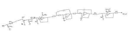
The output buffer is useless.
The polarity of the 22 uF electrolytic capacitor can best be swapped as the bias current of an NE5532 always flows into the input, drawing the op-amp input slightly negative.
The bottom side of the 47 pF should go to ground.
Otherwise it looks fine to me.
The polarity of the 22 uF electrolytic capacitor can best be swapped as the bias current of an NE5532 always flows into the input, drawing the op-amp input slightly negative.
The bottom side of the 47 pF should go to ground.
Otherwise it looks fine to me.

I saw on Rod Elliott"s design , he used an output buffer as well, but for gain and the pot at the end. I tought it's used so the amp , impedance, won't mess with the filters performance. Guess I was wrong. Is the 100 ohm on the first buffer to small ? Do i need a 1k res or so, there's usually a higher value there, I assume ,to form a low pass with the cap ( usually 220p or so ) to gnd ?. Block AM , RF.The output buffer is useless.
I'm not so experienced working with op amps.
Thanks.
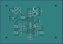
I would connect the unused op-amp as a voltage follower with grounded input. Everything else looks fine to me.

Neither is anyone else, that's just the problem 😉
Chances are that an unconnected op-amp will just clip to a rail, but when it happens to have a particularly small offset voltage, it might as well oscillate or amplify its own noise by its open-loop gain. If its output signal then crosstalks to the signal path, you get a hard to reproduce and quite unnecessary performance degradation.
Hence my preference for connecting it as a voltage follower. The latest layout looks fine.
Neither is anyone else, that's just the problem 😉
Chances are that an unconnected op-amp will just clip to a rail, but when it happens to have a particularly small offset voltage, it might as well oscillate or amplify its own noise by its open-loop gain. If its output signal then crosstalks to the signal path, you get a hard to reproduce and quite unnecessary performance degradation.
Hence my preference for connecting it as a voltage follower. The latest layout looks fine.
Thank you very much for the explanation and for your time to help.
- Home
- Source & Line
- Analog Line Level
- Need a bit of help - 4th order low pass , volume pot location, buffers, my head hurts.