I'm sure this has been explained somewhere, but I can't find it. Let's say I've got an FM tuner (Sansui 2000x) that uses a conventional 3-stage tuned transformer IF strip with no fixed ceramic filters. Let's say due to component tolerances it gives the best response curve a bit off of 10.7 MHz, say 10.9 MHz. Should one align it at 10.9 or "force" it to 10.7, even if the shape isn't as good? Does this affect anything else, or is the exact IF frequency more or less arbitrary?
I'm sure this has been explained somewhere, but I can't find it. Let's say I've got an FM tuner (Sansui 2000x) that uses a conventional 3-stage tuned transformer IF strip with no fixed ceramic filters. Let's say due to component tolerances it gives the best response curve a bit off of 10.7 MHz, say 10.9 MHz. Should one align it at 10.9 or "force" it to 10.7, even if the shape isn't as good? Does this affect anything else, or is the exact IF frequency more or less arbitrary?
No need to force 10.70 MHz, it is, as you say, more or less arbitrary on tuners that use mechanical methods like air caps, i.e. are manually tuned.
If you do change it from 10.7 to 10.9, though, it will require complete front end re-alignment. Not a big deal if you have the gear. I've seen tube tuners like this, that have a preferred IF tuning for best shape that is off a bit from 10.7, it's not a big deal.
A hint though, make sure that you are not loading the IF tuned circuit with probe capacitance when adjusting or making these measurements. Adding or removing the probe when tuned to a low level FM RF signal at the antenna input, i.e. 2uV, will tell you if you have a problem.
The problem of 10.70 off is with digital tuned, crystal referenced tuners, that "expect" the IF to be exactly 10.70. In some cases there was provision for adjustment. It was usually in discrete steps on the counter chip that divides the frequency of the local oscillator before feeding it to the control chip.
In other cases, there was a variable trim cap in the reference crystal oscillator circuit, allowing adjustment. That's usually how I fix this problem on digital tuners, by adding small value (pf) caps to the circuit in the right place.
Hi Conrad
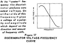
In gross terms for analog tuners, as long as you will tune the subsequent discriminator for producing 0V at the desired IF frequency (that is, the S curve to be centered at this exact frequency) **, yes it is arbitrary (failure of tuning the discriminator will also affect the AFC and AGC).
If your IF strips are L-C tanks, you can adjust them in terms of coupling and in terms of resonance frequency, so you can achieve desired curves for each strip and desired overall curve by strip staggering.
George
Edit>** provided you don't deviate much from the nominal 10.7MHz, else some sidebands will be favoured. This is why BFNY talks about front end readjustment (LO and mixer)
Attachments
Last edited:
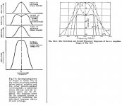
Thanks BFNY! I suspected as much, but am in a bit of a learning mode with RF and didn't want to overlook anything. George, where did you get those charts? They look like Terman but I don't remember seeing them. An exact and deterministic method of tuning the 6 slugs for the desired response has eluded me, though trial and error eventually gets me where I want to go.
Last edited:
There is some discussion and plots here that may be interesting about FM IF alignment. There links to other threads there on probes and equipment are good too.
Antique Radio Forums • View topic - FM Radio Sweep Alignment How To Pictorial
Antique Radio Forums • View topic - FM Radio Sweep Alignment How To Pictorial
This is a basic demo:
Sweep Generator Basics and Receiver Alignment
Sweep Generator Basics and Receiver Alignment - YouTube
George
Sweep Generator Basics and Receiver Alignment
Sweep Generator Basics and Receiver Alignment - YouTube
George
- Status
- Not open for further replies.