Yes you have to extend a flat "gate ribbon" cable connecting the boards inside. NO SOLDERING INVOLVED! Just alot of patience 🙂 and a steady hand. Hey, a guy from Canada did it... that just goes to show you ANYONE can do it 🙂
It's 4:30AM here in BKLYN and I just got home from work. I do have new pics and should have time to countinue the tutorial Monday afternoon. I'll be working all day Sunday into Monday.
Cruser has a nice tutorial posted on dismantling the 1545. Everyone should check it out for some basic know-how on taking LCD's apart. From what I read some parts of the dismantle are easier on the 1545... and some are easier on the 1560M.
jcbklyny, where did you purchase the lcd at? Did they give you any trouble about returning it for one bad pixel? From what I've read, most stores have a policy that allows for a minimal number of bad pixels before the product is "defective". As far as I'm concerned, one is too many.
BTW, thanks for the great thread, I new to diy ohp and I think I'm going to go with the NEC 1560M based on this this reassuring thread.
BTW, thanks for the great thread, I new to diy ohp and I think I'm going to go with the NEC 1560M based on this this reassuring thread.
Straight from Nec's website:
"Our specifications allow 10 missing dots (dead pixels). But, if there is a cluster of some missing dots, we will consider that depending on colors that are missing and distance between the quantity of missing dots. White paper can be found at http://support.necmitsubishi.com/nec/common/library/white_papers.htm"
"Our specifications allow 10 missing dots (dead pixels). But, if there is a cluster of some missing dots, we will consider that depending on colors that are missing and distance between the quantity of missing dots. White paper can be found at http://support.necmitsubishi.com/nec/common/library/white_papers.htm"
I got my 1560 off of googlegear.com ... awesome site, free 2 day shipping, i picked up for 285 US. Of course now you can pick it up for 270. Damn capitalism!
I got it from tech on web. The link should be in this thread somewhere. I expected to have trouble returning it. The rep just wanted to make sure I knew it wasn't their fault... and shipped me a new one right away. No problems.
Although after further testing... on this new one I have found 1 dead RED pixel. You never see it unless you do solid color tests through NEC's software control. I have yet to see it during a movie or normal use... so I can live with it 🙂
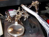
***Flex cable extension update:
I know I promised a no solder fix... but the connection is just not reliable enough for me. Soldering WILL be involved in my fix of the flex cable. I'll be walking you through it as promised and will also give you a complete list of tools you might find make the task easier. I found shielded cable at radio shack perfect for the job (unlike other threads recommending IDE cable).
Since html display isnt working anymore I'm moving the tutorial to a page of it's own with this thread as comment/question's.
***PS:: Anyone who failed at extending the flex cable added resistance to the line. As long as the wire you use doesnt add any resistance... your fix will work. If you use IDE cable rip out all 7 strands and use them unshielded. DO NOT leave them in the shield and have 1 of the 7 exposed on each side. All 7 touch and will add resistance to the line!
Although after further testing... on this new one I have found 1 dead RED pixel. You never see it unless you do solid color tests through NEC's software control. I have yet to see it during a movie or normal use... so I can live with it 🙂
***Flex cable extension update:
I know I promised a no solder fix... but the connection is just not reliable enough for me. Soldering WILL be involved in my fix of the flex cable. I'll be walking you through it as promised and will also give you a complete list of tools you might find make the task easier. I found shielded cable at radio shack perfect for the job (unlike other threads recommending IDE cable).
Since html display isnt working anymore I'm moving the tutorial to a page of it's own with this thread as comment/question's.
***PS:: Anyone who failed at extending the flex cable added resistance to the line. As long as the wire you use doesnt add any resistance... your fix will work. If you use IDE cable rip out all 7 strands and use them unshielded. DO NOT leave them in the shield and have 1 of the 7 exposed on each side. All 7 touch and will add resistance to the line!
Could we possibly strech fine copper wire inbetween two fine tooth combs, having each strand inbetween each tooth....Then pull the wire tight so that each one is seperate. Next you would use wide tape over the top and bottom of the wire. I may be trying to fix a problem that does not exist, but then again, it might just help out.
Like I said, ANY fix will work as long as the lines test for no resistance. The "Tape" method did in fact work... but one wrong tug on the cable and the lines wouldn't touch the contact points. Which is why I wanna solder.
I'm going to try to trace the lines on the PCB's. If I can do that I would take 16 connections down to 9. Every other line out of the 16 is a ground. This is done because of the narrow spacing of the copper on the flex cable (which is actually one solid piece of copper with the spaces etched out). They make every other line a ground to prevent data loss from one line to another.
If I cant find the points on the PCB's I'll just solder the lines directly on the flex cable itself. Which as it turns out is faster then lining the wires up with tape 🙂
jcbklyny, I would like to contact you via email. Could you please send me an email phil@diyprojection.com ?
Thanks
Thanks
I'm not sure what you mean cruser. It's pixel count? 85.5 (per inch)
*And I sent you an email VM.
*And I sent you an email VM.
jcbklyny said:I'm not sure what you mean cruser. It's pixel count? 85.5 (per inch)
*And I sent you an email VM.
im sorry i meant the manufacture part number for the lcd
inside the monitor for example (lg philips lm150X05 A3)
Hi, I'm new here.
Just wondering how this deconstruction project is coming along? I'm eagerly awaiting the final steps. Should it prove successful, I'm planning to install a 1560M into a home built cabinet as per DIY LABS Alan Staples MKII with the double ended 250W MH bulb...unless someone here comes up with a persuasively better design for 1560M use?
Thanks for sharing your project ideas.
I'm just about finished with it. I'm just putting together the final design and hopefully I'll have the time to post it sometime this week. Work should slow down towards the middle of the week... so say wed or thurs...
I noticed on the specs that the the 1560M has integrated USB 2.0 Is this a device input port or just an output to connect to a computer? Can this port be retained and incorporated into the projector case? Reason I ask is because I have a USB 2.0 webcam, but my laptop is only USB 1.1. It still works, but not at the faster fps speeds that a 2.0 port is capable of. If I can keep the NEC's USB port then that would be a big bonus to using this screen.
The base of the monitor is a USB 2.0 Hub. With 3 inputs and 1 output. So yes you can add it to the projector case... alogn with the speakers if you wanted to make the unit portable.
jcbklyny,
got any new pics of your tutorial in progress?
I am amped up about this project, but cant bring
myself to buy a 1560 til I see your methods.
Thanks,
jarrett
got any new pics of your tutorial in progress?
I am amped up about this project, but cant bring
myself to buy a 1560 til I see your methods.
Thanks,
jarrett
- Status
- Not open for further replies.
- Home
- General Interest
- Everything Else
- The Moving Image
- DIY Projectors
- NEC LCD 1560M Information