yes exactly
Solid state is very tolerable to impedance.
I only use additional compensation if the peak is higher than the reflex peaks.
I have provided additional crossovers to address vertical
or at least improve.
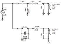
Traditional 4th order linkwitz riley with invert tweet.
Then additional design with 3rd order tweet and woofer notch.

Solid state is very tolerable to impedance.
I only use additional compensation if the peak is higher than the reflex peaks.
I have provided additional crossovers to address vertical
or at least improve.
Traditional 4th order linkwitz riley with invert tweet.
Then additional design with 3rd order tweet and woofer notch.
Attachments
Last edited:
Assuming that the mic is on tweeter axis (0,0,0) the coordinate Y in the woofer section of the crossover tab should not be zero but equal to the C-C distance (negative) between W and T.

@shadowplay62 thanks for the tip, do you know what the common way to simulate diffraction is in VituixCAD? Im trying to figure out the proper mic placement in the diffraction tool? Should I place the mic in the theoretical mid of both drivers, or on axis of each, or on axis of the tweeter when simulating? See pictures for reference

#2 is the correct one.
Kimmo recommends to perform measurements on axis for every driver and input the coordinates x,y,z in the main program so the correct travel time from speaker to mic is calculated.
Anyway, for small baffles like yours you can perform all the drivers measurements with the mic in a fix position (i.e. on axis wih T or at halfway between W and T) and accordingly input the coordinates in Vituixcad.
Also adjust the typical listening distance in the Room tab.
Thanks, did so and think I come to finalize my design soon. Im very happy with the predicted responses I got now.
For impedance compensation I think I am just gonna invest the couple of euros for the parts to make sure it's right.
Thanks for everyone and their help so far. Learned a lot.
If anyone could be so kind to have a look over it again and tell me if I'm blankly missing something, it'd be appreciated.

For impedance compensation I think I am just gonna invest the couple of euros for the parts to make sure it's right.
Thanks for everyone and their help so far. Learned a lot.
If anyone could be so kind to have a look over it again and tell me if I'm blankly missing something, it'd be appreciated.
If you are taking one measurement on axis and then adding simulated diffraction, there can be discrepancies. Breakup is not simulated and is difficult to predict. Then there's the on-axis response being different to the other axes. Also will VC be contributing the piston size related lobing?
If unsure, be particular to cross outside the breakup region.
If unsure, be particular to cross outside the breakup region.
- Home
- Loudspeakers
- Multi-Way
- Nearfield Speaker using RS150P-8A ND25FW-4 Crossover Design