Hello guys,
I am looking for an experienced speaker designer that could have a look at my crossover.
I currently own C-Note's that I built some time ago but unfortunately my woofers have developed voice-coil rub after I turned them too loud on a party.
This inspired me to design a speaker by myself. I like the tweeters which is why I want to keep them and like the idea of having a waveguide for directivity.
So I want to upgrade on the woofers and chose the RS150P.
I looked at other designs using them like the "C-Killa" by Rob Elder which I took inspiration of since my enclosure design, by 1 liter, is just slightly bigger than his.
I adjusted some values for the woofer to make it more fitting for the Paper version. I want to try to keep as many crossover parts of the original C-Note as possible.
Crossover is adjusted for baffle-step. Just trying to check if there is anything entirely wrong with the crossover. The impedance curve looks kinda wonky imo, should I worry about that?

Appreciate any help I can get. Thanks for your time!
I am looking for an experienced speaker designer that could have a look at my crossover.
I currently own C-Note's that I built some time ago but unfortunately my woofers have developed voice-coil rub after I turned them too loud on a party.
This inspired me to design a speaker by myself. I like the tweeters which is why I want to keep them and like the idea of having a waveguide for directivity.
So I want to upgrade on the woofers and chose the RS150P.
I looked at other designs using them like the "C-Killa" by Rob Elder which I took inspiration of since my enclosure design, by 1 liter, is just slightly bigger than his.
I adjusted some values for the woofer to make it more fitting for the Paper version. I want to try to keep as many crossover parts of the original C-Note as possible.
Crossover is adjusted for baffle-step. Just trying to check if there is anything entirely wrong with the crossover. The impedance curve looks kinda wonky imo, should I worry about that?
Appreciate any help I can get. Thanks for your time!
Did you simulate the baffle in full space?
looks like half space from driver data.
coil values dont seem right for whatever impedance the drivers are crossing
so your getting a huge peak.
would drive me nuts, usually have no peaks
amplifiers, especially a tube amp would hate it.
looks like half space from driver data.
coil values dont seem right for whatever impedance the drivers are crossing
so your getting a huge peak.
would drive me nuts, usually have no peaks
amplifiers, especially a tube amp would hate it.
Last edited:
There's not enough information here to be sure, so it's good you are not doing anything drastic. At first glance, the woofer dip near 1kHz looks unnecessary.
Far as I know C note baffle is 190mm x 279mm
Exactly the filter on woofer looks weird as well.
assuming magical tiny baffles.
the step could be around 500 where that filter is
Exactly the filter on woofer looks weird as well.
assuming magical tiny baffles.
the step could be around 500 where that filter is
Last edited:

Well you cant design a crossover unless you take in account the actual baffle step.
and phase response on the specific baffle being used.
I can get these drivers to sum, but the vertical is pretty much awful.
Dayton is incredible nice to provide Frd files.
But getting these to sum on a 8 foot NEC test baffle would be rather easy.
Getting them to sum on a itsy bitsy baffle is different story
and your taking into account the on axis response only.
tells you nothing about what is really happening.
if you get a 50 ohm peak then the coil values are miles off
sounds negative I know, but the goal is very for positive results
Further info... The C-Killa were a design by Lou that he gave his doctor when he was treating him for cancer. Ditto what Ed said. I miss Lou....

Im sorry about mixing up the speaker designer, all credits to Louis. May he rest in peace.
The baffle I have in mind is 200x300 (WxH)
Yes, I implemented that because of the baffle simulation, it said there would be an 8db boost in the 1khz region.There's not enough information here to be sure, so it's good you are not doing anything drastic. At first glance, the woofer dip near 1kHz looks unnecessary.
The baffle I have in mind is 200x300 (WxH)
Thanks for your design. Have you done it based on the official dayton frd's?It is difficult in vertical.
Impedance curve seems normal now
Even parts express crossover has huge 30 ohm peak.
View attachment 1167716
View attachment 1167717
View attachment 1167720
If so, baffle step compensation is not applied, right? Or am I missing something?
full space simulation at 1 meter
Drivers positioned accordingly on mentioned c note 190mm x 279mm baffle
they sum rather easily horizontal.
you will quickly see vertical phase issues
with tweeter phase response inverted or non inverted.
I can get vertical looking very nice with more elaborate design.
both in phase 3rd order.
Required a notch and various impedance compensation.
I posted more simple design, it was driving me nuts
fighting with small baffles drive me crazy LOL
Last edited:
Fair enough. If you want more information you can check the other angles and see whether it represents an average. When it comes to diffraction there are times when you might make adjustments, but when in doubt you might also ignore them.an 8db boost in the 1khz region.
I can see, you were right, I only simulated baffle on half space. Mistake on my side. I now created a merged response using the impact of the enclosure I want to use and the frd file provided by Dayton, also a simulated impedance response in the enclosure, which I missed last time. Still a lot to learn.full space simulation at 1 meter
Drivers positioned accordingly on mentioned c note 190mm x 279mm baffle
they sum rather easily horizontal.
you will quickly see vertical phase issues
with tweeter phase response inverted or non inverted.
I can get vertical looking very nice with more elaborate design.
both in phase 3rd order.
Required a notch and various impedance compensation.
I posted more simple design, it was driving me nuts
fighting with small baffles drive me crazy LOL
I came up with the following crossover now, impedance curve looks way better
exactly, took it from @WhiteDragon's design and adjusted a bit to make the curve flatter for my chosen components
I can see, you were right, I only simulated baffle on half space. Mistake on my side. I now created a merged response using the impact of the enclosure I want to use and the frd file provided by Dayton, also a simulated impedance response in the enclosure, which I missed last time. Still a lot to learn.
I came up with the following crossover now, impedance curve looks way betterView attachment 1167801
nice nice much better
small learning curve using diffraction tool in Virtuix cad.
but it will make baffle simulation much easier.
and generate 0 to 90 degree responses for you.
vertical and horizontal.
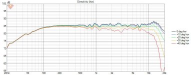
This is with simulated directivity responses, for the woofer I simulated 0-90 degrees, dayton only provides 0,15,30,45 for the tweeter tho, is that why theres the big dips starting at 50 degrees?

yep there you go.
0 degree easy to sum. but once you see everything you start getting dips off axis.
diffraction tool simulates driver position on baffle and phase according to the
listening position.
using factory FRD is based on huge test baffle.
need be looking at exact driver position on specific baffle size.
0 degree easy to sum. but once you see everything you start getting dips off axis.
diffraction tool simulates driver position on baffle and phase according to the
listening position.
using factory FRD is based on huge test baffle.
need be looking at exact driver position on specific baffle size.
- Home
- Loudspeakers
- Multi-Way
- Nearfield Speaker using RS150P-8A ND25FW-4 Crossover Design