Just to mention to the late builders (like me) the NE5532's that were available when i purchased them were the NE5532AP.
http://uk.farnell.com/texas-instruments/ne5532ap/op-amp-dual-low-noise-5532-dip8/dp/1106091?ost=NE5532AP&ddkey=http%3Aen-GB%2FElement14_United_Kingdom%2Fsearch
You'll see here the supply voltage range is +5v - 15v.
The Elektor project has 17v supplies from the PSU.
In the above technical sheet for this i.c. it shows max. voltage is 22v, but recommended supply is 15v.
I wrote to Elektor explaining this and they told me to play it safe reduce R2 & R4 from 1.3k to 1.1k, which i have done, reducing the PSU o/p from 17 to 15v.
In Elektor 06-2012, page 26, it give information of 'Miscellaneous - Not on PCB'.
Can someone clear up what is written of the fuse F1 (230VAC) = fuse, 0.315A Antisurge?
What is the correct mains input fuse that should be used on the mains input circuit?
Can someone clear up what is written of the fuse F1 (230VAC) = fuse, 0.315A Antisurge?
What is the correct mains input fuse that should be used on the mains input circuit?
What is the rating of the mains transformer?
That determines the fuse rating.
eg.
230Vac 100VA uses ~ 100/230 = 0.43A and would need a close rated fuse of about 500mA. i.e. T500mA
That determines the fuse rating.
eg.
230Vac 100VA uses ~ 100/230 = 0.43A and would need a close rated fuse of about 500mA. i.e. T500mA
Last edited:
In Elektor 06-2012, page 26, it give information of 'Miscellaneous - Not on PCB'.
Can someone clear up what is written of the fuse F1 (230VAC) = fuse, 0.315A Antisurge?
What is the correct mains input fuse that should be used on the mains input circuit?
I have just answered this in another thread you posted to.
 Please don't keep posting the same questions to multiple threads, its as bad as starting two threads in the hope of getting quicker answers.
What is the rating of the mains transformer?
That determines the fuse rating.
eg.
230Vac 100VA uses ~ 100/230 = 0.43A and would need a close rated fuse of about 500mA. i.e. T500mA
The surge may be too much for a 500mA unless you use an anti surge fuse. I would start with a 1A.
What is the rating of the mains transformer?
That determines the fuse rating.
eg.
230Vac 100VA uses ~ 100/230 = 0.43A and would need a close rated fuse of about 500mA. i.e. T500mA
T500mA is a Time delayed fuse. That is what the "T" tells me.The surge may be too much for a 500mA unless you use an anti surge fuse. I would start with a 1A.
I think the other posts have all had replies to them and so it would not be fair to delete them now.
Just remember to ask the one question in the appropriate thread 🙂
Just remember to ask the one question in the appropriate thread 🙂
Ideas please!
I now have the connector inserted into K17 on the Input PCB.
Inserting the other end into the Front Panel PCB into K1 socket it's now impossible to have the Front Panel PCB flush up against my metal case front panel, due to the size of the plug & socket.
Any ideas on what i can use to be able to mount my Front Panel PCB as it'll have to fall back a few centimeters?
Apart from that wiring nearly finished.
In Elektor April '12, page 22, it states: -
'Axial polystyrene caps require care in determining where to bend the legs. Their size is not standardized and subject to various tolerances compared to other parts.'
Can someone kindly enlighten me about this.
'Axial polystyrene caps require care in determining where to bend the legs. Their size is not standardized and subject to various tolerances compared to other parts.'
Can someone kindly enlighten me about this.
Also check out the comment in:
-
hthttps://www.elektormagazine.com/labs/preamplifier-2012-1-introduction-and-line-intonevolume-board-110650tp://
more noise reduction
if you insert a 100-Ohm resistor between each 17V-line to OpAmp (and elko behind resistor), so you can reduce noise coming from 17V stabilisator. If you don't use a stabi, so ist must not be - if you can eliminate all noise and hum from 17V.
In Elektor April '12, page 22, it states: -
'Axial polystyrene caps require care in determining where to bend the legs. Their size is not standardized and subject to various tolerances compared to other parts.'
Can someone kindly enlighten me about this.
A picture is worth a lot:-
How would you bend these (very thin) wires to fit a pcb?
Attachments
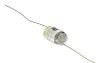
Appreciate the picture (though can't zoom in), though i was suspecting something a bit mysterious.
Clearly, it's just a matter of taking care where to bend the legs so they then align with the holes they have to fit through
Clearly, it's just a matter of taking care where to bend the legs so they then align with the holes they have to fit through
sorry, pic lifted from a supplier's catalogue page!
I am not sure anyone still makes this sort of polystyrene cap anymore. This style is very much pre-automation (caps in a bunch inside a plastic bag, all scrambled up.
We always inserted and soldered them manually on otherwise finished boards. Production people hated that!
I am not sure anyone still makes this sort of polystyrene cap anymore. This style is very much pre-automation (caps in a bunch inside a plastic bag, all scrambled up.
We always inserted and soldered them manually on otherwise finished boards. Production people hated that!
CPC have a healthy list of similar style caps from LCR, although some may be polypropylene. I always called them by the name 'suflex' many many years ago.
Always try and connect the outer foil to the lowest impedance point to get the benefit of shielding and minimise stray pickup.
Always try and connect the outer foil to the lowest impedance point to get the benefit of shielding and minimise stray pickup.
Axial Caps
Farnell still have all the required caps for this project😉
e.g.
http://uk.farnell.com/lcr-components/fscex-220pf-1-630v/cap-film-ps-220pf-630v-axial/dp/9520716?ost=9520716&ddkey=http%3Aen-GB%2FElement14_United_Kingdom%2Fsearch
Interesting to read 'Always try and connect the outer foil to the lowest impedance point to get the benefit of shielding and minimise stray pickup.'
Usually the out foil end is the end that is coloured or marked in some way.
Cheers for that important clarification 😉
the new 5532 and LF353 or TL072 should perform better then old ones as they are made on a smaller die ( lithography ) and therefore would experience higher speed and possibly lower power consumption.
- Status
- Not open for further replies.
- Home
- Amplifiers
- Chip Amps
- NE 5532 PreAmplifier from Doug Self, Elektor 2012