
Here is the final version.
Added input filter and Zobel output.
Added an opamp for DC Servo to zero the output.
To set bias in the output select R13 and R14 for like 200mA bias.

Added input filter and Zobel output.
Added an opamp for DC Servo to zero the output.
To set bias in the output select R13 and R14 for like 200mA bias.
There are ways.
But DC Servo is the best precision.
Witth Other ways the DC can be floating with the temperature.
But DC Servo is the best precision.
Witth Other ways the DC can be floating with the temperature.
Job done
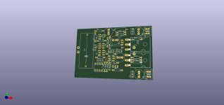
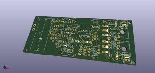
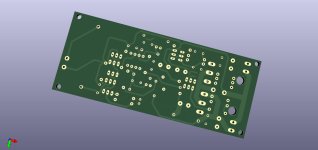
I added zener diode resistors and decoupling capacitors around the dc-servo Op-AMP, (now we can use a higher supply voltage)
I also added decoupling capacitors on the power lines
Grounds separated into signal and dirty lines.
Power transistors mounted under the PCB.
The board is 118x48mm.
We can use cheap radiators 150 (or 200)x50mm from Ali...
When the prototype is built, measured and checked (maybe next month) I can share the gerber files - if anyone is interested
Attachments
Your Cello Amp is also great!
I have "regular" power Amp and modded jfet input headphone version😁
Navajo is the next!
I have "regular" power Amp and modded jfet input headphone version😁
Navajo is the next!
I like you @ZoltanChivay
And it is gold for me to have people like you. Who believe in my work.
And who can design PCB. You are a true diy member.
I must now go back to my CELLO. Maybe push it a little 😀
And it is gold for me to have people like you. Who believe in my work.
And who can design PCB. You are a true diy member.
I must now go back to my CELLO. Maybe push it a little 😀

Unfortunately, for personal reasons I have to suspend my DIY activity for a few weeks.
Stay tuned
Stay tuned
I was interested in this circuit as the output is (almost) a non-switching type. However, I think there is an issue that needs addressing, though it does appear to have a simple fix.
1) Looking at the output currents in Mooly’s Draft3 V3.asc (from post 24), with R9=R10=22R, the lower half of the output is clearly non-switching, with a minimum current of around 16mA, but the upper half has a minimum current of only 2.7mA – see Fig1.jpg.

The fix is to massage R9 & R10 to balance the two halves of the output circuit. For example, simply changing R10 to 47R equalises the minimum currents passed by each output device, which is now around 50mA – see Fig2.jpg. Unfortunately, this increases Iq from 182mA to 262mA. Personally, I think that is a small price to pay for robust NSB performance.

I’m not sure if this is due to real differences between pnp and npn transistors or whether there is some sort of inaccuracy in the models. The values of R9/R10 can always be finalised on a prototype.
2) As some posters have questioned the thermal performance of this circuit, I also had a look at the effects of different temperatures on these currents. Unfortunately, setting the local temperature for Q6 & Q7, with BC456B and BC556B specified, prevents the sim from running – LTspice complains about a singular matrix. The models for 2N2907 and 2N2222 do show the correct c. 2mV decrease in Vbe per deg C, so I swapped out Q6 & Q7 for these just to gauge Iq vs. temp.
I had a look at three thermal mechanisms that could influence Iq: a) change in temperature of Q6 & Q7 only; b) change in temperature of M1 & M2 only; c) change in temperature when drivers on same heatsinks as output devices. In all three cases, Iq actually decreases as the devices warm up. The most stable Iq performance is achieved when Q6/Q7 are not thermally coupled to M1/M2. When R10=47R, Iq falls to 246mA when M1/M2 are at 70deg (from 262mA at 27deg C). Iq decreases by around 0.4 mA for every deg C increase in temperature in M1/M2. Despite the negative temp coefficient of Iq, if R10=47R, non-switching is maintained at all audio frequencies, output levels and temperatures. Not bad.
3) Given that a dc servo has been added, is C2 still necessary?
1) Looking at the output currents in Mooly’s Draft3 V3.asc (from post 24), with R9=R10=22R, the lower half of the output is clearly non-switching, with a minimum current of around 16mA, but the upper half has a minimum current of only 2.7mA – see Fig1.jpg.
The fix is to massage R9 & R10 to balance the two halves of the output circuit. For example, simply changing R10 to 47R equalises the minimum currents passed by each output device, which is now around 50mA – see Fig2.jpg. Unfortunately, this increases Iq from 182mA to 262mA. Personally, I think that is a small price to pay for robust NSB performance.
I’m not sure if this is due to real differences between pnp and npn transistors or whether there is some sort of inaccuracy in the models. The values of R9/R10 can always be finalised on a prototype.
2) As some posters have questioned the thermal performance of this circuit, I also had a look at the effects of different temperatures on these currents. Unfortunately, setting the local temperature for Q6 & Q7, with BC456B and BC556B specified, prevents the sim from running – LTspice complains about a singular matrix. The models for 2N2907 and 2N2222 do show the correct c. 2mV decrease in Vbe per deg C, so I swapped out Q6 & Q7 for these just to gauge Iq vs. temp.
I had a look at three thermal mechanisms that could influence Iq: a) change in temperature of Q6 & Q7 only; b) change in temperature of M1 & M2 only; c) change in temperature when drivers on same heatsinks as output devices. In all three cases, Iq actually decreases as the devices warm up. The most stable Iq performance is achieved when Q6/Q7 are not thermally coupled to M1/M2. When R10=47R, Iq falls to 246mA when M1/M2 are at 70deg (from 262mA at 27deg C). Iq decreases by around 0.4 mA for every deg C increase in temperature in M1/M2. Despite the negative temp coefficient of Iq, if R10=47R, non-switching is maintained at all audio frequencies, output levels and temperatures. Not bad.
3) Given that a dc servo has been added, is C2 still necessary?
Hi @lineup (and others),
in LTSpice the Navajo looks really (I mean: really, really) nice. I have some questions on the DC servo though.
Some questions regarding the DC servo in that place. My knowledge is rather rudimentary, so bear with me, if my questions are too far off.
1) The servo is not providing a DV value, but a rather high amplitude AC with a correct DC offset. Can't feeding that into the NFB point negatively effect the overall performance?
2) The feedback signal coming through the 220uF-33k is then connected to the 47k at the output of the servo, and from there via the 0.22uF capacitor will also affect the output signal of the DC srvo OpAmp, right?
3) The AC part of the voltage from the servo signal has a phase shift compared to the NFB signal, which I guess is also not desired and might add to the above.
Are these concerns, valid, neglectible?
I played around in Spice and added a unity gain buffer after the DC servo OpAmp. It seems to work equally well WRT controlling DC. The results was very slightly higher (really almost identical) total THD, but nicer, cleaner falling harmonic amplitudes.
The signal from my modified servo circuit has a much (much) lower AC part, so should affect the amp much less.
Thanks,
Moz
- Home
- Amplifiers
- Solid State
- Navajo - 16 Watt Diamond with low distortion