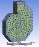
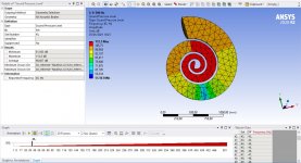
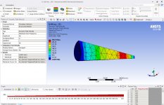
I am performing finite element analysis over a Nautilus speaker enclosure design.
The premises and objectives are:
- Analice golden spiral box for speaker usage
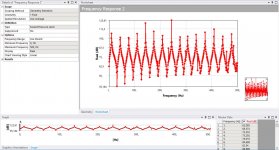
- To observe and analice the resonances, gains and phase shifts of this type of enclosure through a sound sweet from 0 to 500Hz.
- 12" size speaker, and make the logarithmic spiral from there.
I made tree scenarios regarding internal air volume from the original design of 228 litres, 114 and 57 litres. The surprise is the differences I saw regarding internal resonances. Let me share some pictures and videos.
I would like to ask you if you have some insight about why the number of resonance frequencies are severally atenuated when the enclosure volume is divided. They will be attenuated with some stuffing material, but the point is to achieve as flat as posible response from the beginning.
I will be available to provide any further information about the simulation
The premises and objectives are:
- Analice golden spiral box for speaker usage
- To observe and analice the resonances, gains and phase shifts of this type of enclosure through a sound sweet from 0 to 500Hz.
- 12" size speaker, and make the logarithmic spiral from there.
I made tree scenarios regarding internal air volume from the original design of 228 litres, 114 and 57 litres. The surprise is the differences I saw regarding internal resonances. Let me share some pictures and videos.
I would like to ask you if you have some insight about why the number of resonance frequencies are severally atenuated when the enclosure volume is divided. They will be attenuated with some stuffing material, but the point is to achieve as flat as posible response from the beginning.
I will be available to provide any further information about the simulation
Attachments
-
 Design.JPG69.5 KB · Views: 399
 -
 57_Sound Pressure dB.JPG67.8 KB · Views: 149
 -
 114_Sound Pressure dB.JPG82.7 KB · Views: 190
 -
 228_Sound Pressure_62Hz_38dB.JPG179.8 KB · Views: 399
 -
 228_Sound Pressure_45Hz_100dB.JPG183.8 KB · Views: 400
 -
228_Sound Pressure_374Hz_100dB.mp42.9 MB
-
228_Sound Pressure_45Hz_100dB.mp42.2 MB
-
 228_Sound Pressure dB.JPG177.3 KB · Views: 366
 -
 228_Acoustic Pressure MPa.JPG227.5 KB · Views: 374
Last edited:
Quick clarification:
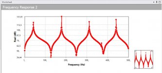
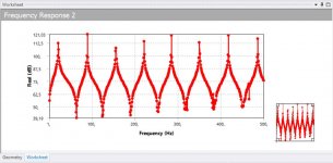
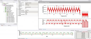
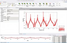
- 15 resonant frequencies between 0-500Hz -> 228 litres enclosure
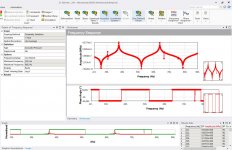
- 8 resonant frequencies between 0-500Hz -> 114 litres enclosure
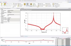
- 4 resonant frequencies between 0-500Hz -> 57 litres enclosure
The videos just shown how where the resonances are located at two example frequencies. Those are where the peaks occurs.
The measurements are done at the speaker surface, just to analice the backwave at the speaker surface.
- 15 resonant frequencies between 0-500Hz -> 228 litres enclosure
- 8 resonant frequencies between 0-500Hz -> 114 litres enclosure
- 4 resonant frequencies between 0-500Hz -> 57 litres enclosure
The videos just shown how where the resonances are located at two example frequencies. Those are where the peaks occurs.
The measurements are done at the speaker surface, just to analice the backwave at the speaker surface.
> why the number of resonance frequencies are severally atenuated when the enclosure volume is divided.
The short length gives resonance every 120Hz. The longer lengths every 60 or 30Hz. 120Hz fits in 0-500Hz just 4 times.
The short length gives resonance every 120Hz. The longer lengths every 60 or 30Hz. 120Hz fits in 0-500Hz just 4 times.
In case you have not sen this. It is the original invention that B&W used in their nautilus Product.
Google us2293181 pdf.
Google us2293181 pdf.
Well, I knew some of the principles of the Nautilus speaker, but i didn't read the patent papers. I found one of your post where you uploaded them. I take some good tips, very interesting tips regarding dimension relations.
DIY Walsh driver revisited
I still need to find out how to model the stuffing material in Ansys workbench, and I will be ready to perform really serious simulations.
I have made a digital version of the Fostex FE-164 ML TQWT and the results where close to real measures, except for some resonant appearing because of the lack of stuffing material on the digital model.
https://www.tiffe.de/roehren/ML_TQWT.pdf
Hope to continue improving digital model with the damping material in order to achieve the digital twin.
Last edited:
Very good!
I forgot to say that it’s a very interesting analysis you are doing! I’m looking forward to see your findings.
Thomas
I forgot to say that it’s a very interesting analysis you are doing! I’m looking forward to see your findings.
Thomas
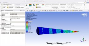
This morning i worked over the tapered tubes, according to nautilus papers specification.
Premises:
- Low Mid: 100mm, XO: 220 - 880 Hz
- Tube long: <= 6x diameter
- Taper rate: >=25 %
- Aperture similar to the speaker diameter
- Sound absorbing material: Not contemplated in simulation (to be done)
- Tapered shape will increase air velocity
- Absorbing material will work better with higer air velocity
- Should be able to eliminate back wave with small back cavity in litres.
Scenarios to understand implications:
Scenario 1:
Taper rate: 25 %
Tube Long: 600mm
Mode 1: 375 Hz
Scenario 2:
Taper rate: 25 %
Tube Long: 1200mm
Scenario 3:
Taper rate: 25 %
Tube Long: 300mm
Scenario 4:
Taper rate: 10 %
Tube Long: 600mm
Mode 1: 404 Hz
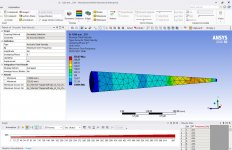
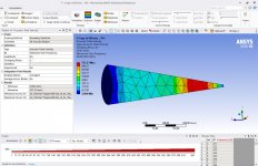
Findings:
- Average dB at speaker level is the same
- Longer tube; Number of resonance modes is increased. Max, min and average dB is constant.
- Longer tube; small change in air velocity.
- Smaller diameter at the back of the tube creates slight movement of the resonant modes frecuency. Little impact in dB
- Smaller diameter at the back of the tube creates much higher air velocities. from 25% diameter to 10% diameter, almost doubles the air velocity: 300mm/s to 600mm/s
Note also the high velocity difference between speaker side and backside.
- Absorbing material will work better with high air velocities.
- ¿Absorbing material will work removing high peaks of resonance modes.?
- Therefore, longer tubes, will have flatter response, less backwave distortion
Next scenarios:
- The resonant frequencies are created after bouncing at the back small circle of the enclosure. -> Create shapes at back trying to break the sound waves (spherical back, triangular shapes, longer cylindrical part at the end, etc.)
- Incorporating sound absorbing material to simulations. Sill struggling to achieve this in ansys workbench.
Premises:
- Low Mid: 100mm, XO: 220 - 880 Hz
- Tube long: <= 6x diameter
- Taper rate: >=25 %
- Aperture similar to the speaker diameter
- Sound absorbing material: Not contemplated in simulation (to be done)
- Tapered shape will increase air velocity
- Absorbing material will work better with higer air velocity
- Should be able to eliminate back wave with small back cavity in litres.
Scenarios to understand implications:
Scenario 1:
Taper rate: 25 %
Tube Long: 600mm
Mode 1: 375 Hz
Scenario 2:
Taper rate: 25 %
Tube Long: 1200mm
Scenario 3:
Taper rate: 25 %
Tube Long: 300mm
Scenario 4:
Taper rate: 10 %
Tube Long: 600mm
Mode 1: 404 Hz
Findings:
- Average dB at speaker level is the same
- Longer tube; Number of resonance modes is increased. Max, min and average dB is constant.
- Longer tube; small change in air velocity.
- Smaller diameter at the back of the tube creates slight movement of the resonant modes frecuency. Little impact in dB
- Smaller diameter at the back of the tube creates much higher air velocities. from 25% diameter to 10% diameter, almost doubles the air velocity: 300mm/s to 600mm/s
Note also the high velocity difference between speaker side and backside.
- Absorbing material will work better with high air velocities.
- ¿Absorbing material will work removing high peaks of resonance modes.?
- Therefore, longer tubes, will have flatter response, less backwave distortion
Next scenarios:
- The resonant frequencies are created after bouncing at the back small circle of the enclosure. -> Create shapes at back trying to break the sound waves (spherical back, triangular shapes, longer cylindrical part at the end, etc.)
- Incorporating sound absorbing material to simulations. Sill struggling to achieve this in ansys workbench.
Attachments
-
 1200mm_25perc_SoundVelocity.JPG204.1 KB · Views: 120
 -
 600mm_25perc_SoundVelocity.JPG199.2 KB · Views: 126
 -
 300mm_25perc_SoundPressure dB.JPG181.7 KB · Views: 123
 -
 600mm_25perc_SoundPressure dB.JPG197.6 KB · Views: 113
 -
 1200mm_25perc_SoundPressure dB.JPG197.6 KB · Views: 98
 -
 1200mm_10perc_SoundVelocity.JPG151.5 KB · Views: 109
 -
 600mm_10perc_SoundVelocity.JPG204.4 KB · Views: 119
Last edited:

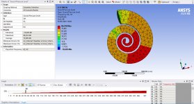
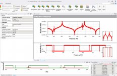
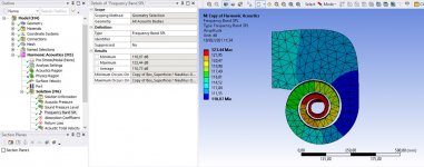
Extracted from Nautilus papers:
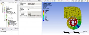
Since change in area is exponentianlly smooth, there is no abrupt discontinuity in acoustic impedance to cause reflections anywhere along the horn except at the far end. As they are no reflections in other place, the absorbent material will attack all resonant with increased efficiency thanks to elevated air velocity. According Nautilus papers, a reduction around 115dB is expected once sound absorbant is in place.
Attached images of Resonances at back end, and at the speaker.
Attachments
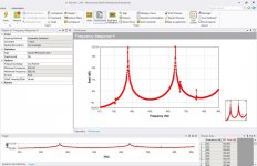
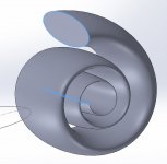
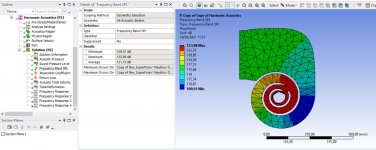
Coming back to the logarithmic spiral parto of the nautilus, some other conclusions:
1. Just as the Nautilus papers mentioned, the shape of the nautilus could be different from a perfect tapered tube.
Making different approach as all other nautilus shaped 3d models around internet, which are just perfect logarithmic tube shape, I implemented oval shape to the length. Attached picture.
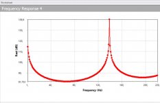
2. The rear reflection have the same shape and the frequency in which appear is the same.
3. We do have an improvement: The overall volume of the enclosure is almost the double. As happens in sealed enclosures, this gives improvement in the lower end response.
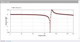
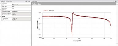
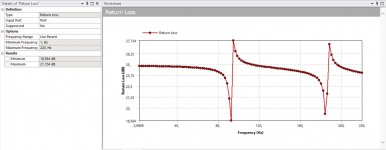
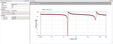
4. I am looking for the return loss. I suspect that this shape gives hell of a lot attenuation of the back wave as is, even without damping material. A am obtaining -20 db over the back wave. I will make another box model for a typical box enclosure to compare the return loss.
I made some improvements about damping material in ansys software. On the other hand, i also learned how to use HornResp and I am quite happy with some correlations and improvement I could do. I helps a lot to do general asumptions, and then make detailed view with finite element 3D model and try to improve the model.
1. Just as the Nautilus papers mentioned, the shape of the nautilus could be different from a perfect tapered tube.
Making different approach as all other nautilus shaped 3d models around internet, which are just perfect logarithmic tube shape, I implemented oval shape to the length. Attached picture.
2. The rear reflection have the same shape and the frequency in which appear is the same.
3. We do have an improvement: The overall volume of the enclosure is almost the double. As happens in sealed enclosures, this gives improvement in the lower end response.
4. I am looking for the return loss. I suspect that this shape gives hell of a lot attenuation of the back wave as is, even without damping material. A am obtaining -20 db over the back wave. I will make another box model for a typical box enclosure to compare the return loss.
I made some improvements about damping material in ansys software. On the other hand, i also learned how to use HornResp and I am quite happy with some correlations and improvement I could do. I helps a lot to do general asumptions, and then make detailed view with finite element 3D model and try to improve the model.
Attachments
Last edited:
Removed because additional search needed fro conclusions.
Attachments
-
 Nautilus Feedback 2 _ Return Loss.JPG90 KB · Views: 82
 -
 Nautilus Feedback 2 _ Frecuency band.JPG157.2 KB · Views: 81
 -
 Nautilus Feedback 1 _ Return Loss.JPG95.5 KB · Views: 86
 -
 Nautilus Feedback 1 _ Frecuency band.JPG151.2 KB · Views: 92
 -
 Nautilus Base _ Return Loss.JPG89.7 KB · Views: 96
 -
 Nautilus Base _ Frecuency band.JPG149.3 KB · Views: 84
Last edited:
Please, don't pay much attention to previous images, I had to increase meshing refinement for improved results.
I already have the first final draft of the spiral subwoofer.
I changed the spiral shape from that conical end to and circular shape. It is now equal to the shape of the original Nautilus, and as improvement, it also adds about 2-3 air litres.
I also completed to model de superior shape area. It have different appearance from the original Nautilus, because this model is half the height while still uses 12" driver with around 50 air litre. Digital DSP, XO around 220Hz.
The next step is the enclosure for the Mid Woofer and Tweeter
I will take the shape of the Nautilus 801. The driver size of this speaker is 5", but I have doubts if I should keep this size or jump into 6" driver.

I think the directionality or polar response around >4-5Khz will be better with a 5" driver but on the other hand, they will probably handle less power.
Thinking about the tweeter I could possibly XO at 3Khz so again, I hesitate about 5 o 6 inch driver for the mids.
I changed the spiral shape from that conical end to and circular shape. It is now equal to the shape of the original Nautilus, and as improvement, it also adds about 2-3 air litres.
I also completed to model de superior shape area. It have different appearance from the original Nautilus, because this model is half the height while still uses 12" driver with around 50 air litre. Digital DSP, XO around 220Hz.
The next step is the enclosure for the Mid Woofer and Tweeter
I will take the shape of the Nautilus 801. The driver size of this speaker is 5", but I have doubts if I should keep this size or jump into 6" driver.
I think the directionality or polar response around >4-5Khz will be better with a 5" driver but on the other hand, they will probably handle less power.
Thinking about the tweeter I could possibly XO at 3Khz so again, I hesitate about 5 o 6 inch driver for the mids.
So, which size do you think will be better for the mids?
- Home
- Design & Build
- Construction Tips
- Nautilus Speaker - Finite element simulation