Your circuit:
Mr Troels may get very cross with me, but TBH, given good FRD and ZMA files, I wouldn't find it hard to reverse engineer his SBA-16-MTM design. 😎
It's such a simple crossover, and he has doubtless got most aspects right, especially slope...
SBA-16-MTM
What you have done is effectively used a first order tweeter, which is very bad for letting the tweeter Fs get out of control and cause excessive excursion at the Fs frequency. I would guess tweeter R1 and R6 are about 2.2R or 3.3R for 9R impedance at high frequency for a start.
You've just got to match his FR and Impedance curves and all will fall into place. 😀
Last edited:
#System7 so it sounds like you think I should expend some effort here as I should be able to improve here. Is there anything I could do quick and dirty just to see if I am going in the right direction? For example the tweeter circuit?
I agree with wolfie.
It's getting past my bedtime, but this second order Madisound design is useful if a bit fussy and has a similar tweeter coil:
Satori MW16P-8 + Seas Crescendo T29CF-002 2way Passive Crossover Design - Madisound Speaker PDF Library
This is a third order:
Satori MW16P + D2904-7100 2way Passive Crossover Design - Madisound Speaker PDF Library
Both end up LR2 12db/octave with deep reverse null. Both have a presence notch on the midbass which usually lets you get away with smaller bass coil, But a presence notch in an MTM takes impedance very low, so probably not an option. To convert them to MTM you halve resistors and coils, and double capacitors in the bass circuit and make the tweeter louder.
Last edited:
That's very impressive Mr. Jim.
Close correlation to Mr. Troels' design. Couple of things disturb me.
Firstly your polarity looks wrong. It is positive polarity usually with 6" drivers. Is your driver offset right? About 30mm difference between the bass and tweeter usually.
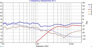
Second, you aren't getting much rolloff. Only about 9dB per octave. 5Khz breakup is only 15dB down. Look for 20dB.
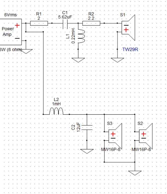
I would try a 1mH coil here with 12uF. Also reinstate a 2.2R in Troels' R6 position after the tweeter coil. This helps keep impedance up. Tweeter values I'd try would be 5.6uF with 0.22mH. Again about right for impedance. Should end up about 1.7 kHz crossover with a downward slope.
Close correlation to Mr. Troels' design. Couple of things disturb me.
Firstly your polarity looks wrong. It is positive polarity usually with 6" drivers. Is your driver offset right? About 30mm difference between the bass and tweeter usually.
Second, you aren't getting much rolloff. Only about 9dB per octave. 5Khz breakup is only 15dB down. Look for 20dB.
I would try a 1mH coil here with 12uF. Also reinstate a 2.2R in Troels' R6 position after the tweeter coil. This helps keep impedance up. Tweeter values I'd try would be 5.6uF with 0.22mH. Again about right for impedance. Should end up about 1.7 kHz crossover with a downward slope.
I made some changes per your suggestions. My baffle is a flat panel with no offset. I did not account for that in XSim. So I assume I should represent the tweeter being "30 mm" ahead of the mids?
I have the absolute polarity of the mids as positive and inverted the tweeter polarity. I played with the polarity looking for a deep null but it is so-so. I have heard mixed opinions on time alignment. Some say it is important other say not so much. I guess if I have to I can make new baffles, but that would be awhile.
I have the absolute polarity of the mids as positive and inverted the tweeter polarity. I played with the polarity looking for a deep null but it is so-so. I have heard mixed opinions on time alignment. Some say it is important other say not so much. I guess if I have to I can make new baffles, but that would be awhile.
Attachments
How were the measurements done?
Your crossover looks like LR2/LR2, and for this the inverted polarity of tweeter is correct. But this is not much possible with mids and tweeter on a flat straight baffle.
It looks to me it is time to take real dual channel measurements with correctly measured relative phases.
Your crossover looks like LR2/LR2, and for this the inverted polarity of tweeter is correct. But this is not much possible with mids and tweeter on a flat straight baffle.
It looks to me it is time to take real dual channel measurements with correctly measured relative phases.
#Pida right now we are looking at different models. My current speaker was measured at about 3 ft away using Omnimic. On axis.
Another thought. in order to get the tweeter artificially moved back could I do that in the XO? Making the tweeter a 3rd order will that help?
Go third on the woofer too.
Did you say you do not have an offset figured into the simulation? Then this is all for naught.
Later,
Wolf
Did you say you do not have an offset figured into the simulation? Then this is all for naught.
Later,
Wolf
You're not rolling off the woofers fast enough. At least a 1.0mH, and likely 18uF, then maybe a 0.33mH after if going third.
Again- if no offset is factored in, then you have some setup to do.
Wolf
Again- if no offset is factored in, then you have some setup to do.
Wolf
IM have the ability to modify the "delay" in the software. Since the tweeter is physically ahead of the woofer should I represent that as "minus" 30mm delay? Since that is the same amount i need to step it back?
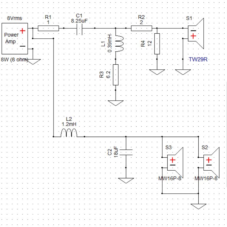
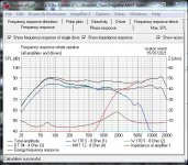
I just had a mess round with this circuit in my simulator working from Troels' ideas:
SBA-16-MTM
It's pretty good. Around 2kHz crossover. I did find the typical acoustic centre offset between midbass and tweeter is actually 40-45mm on flat baffle. Neglect that and indeed negative polarity works best. We are talking about 60 degrees phase error here.
Phase was good on positive polarity with correct acoustic centres.
What worked best for me was bass coil around 1-1.2mH, bass shunt capacitor 18uF.
Tweeter filter is a moveable feast on level. Often a matter of taste. Adjusted by R1. anything between 1R and 3.3R, I suppose.
C1 5.6uF, L1 0.39mH, R2 2.2R.
Adding a 15uF after the tweeter coil for third order will probably work too.
Model away! 😀
(BTW, your midbass frequency response is wrong above 5 kHz in your sims. It shouldn't be rising!)
Last edited:

Offset should be 21mm according to SB Acoustics - https://sbacoustics.com/wp-content/uploads/2018/05/Time-Alignment.pdf
21mm is not enough to explain negative polarity working better in Jim's sim IMO. Who knows? 😀
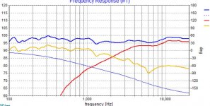
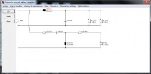
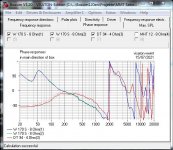
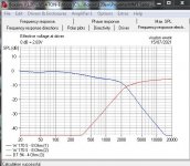
I just reran the sim more accurately. Using "similar" drivers.
Fairly happy with what I saw. Next time I build a 6" plus 1" I may use this idea. Ignore the rise in FR on the DT94-4 tweeter. It is plastic dome, so that's just what it does. Roughly LR2 12dB/octave electrically. Doubtless slighly asymmetric slopes accounting for time delay.
Changing red 1.2mH to 1mH makes it flatter. Tweeter level is adjustable too via the red 2.2R.
Adding a 15uF after the tweeter coil changes phase a bit below crossover towards butterworth and and adds a bit more midrange presence. It also further suppresses the tweeter Fs resonance about 6dB.
Crucially we have lost R3 at 6.2R and reduced the tweeter capacitor value. This is a good thing. Higher order filters sound cleaner. Shouldn't be hard to try this.
Attachments
OK so just to make sure before I make changes I am going to reconfigure my XO as shown and make another baffle with somewhere between 22 and 40mm setback on the tweeter? I use 3/4 stock and can lay layers of stock to bring it to any desired value. Just checking before i move forward
- Home
- Loudspeakers
- Multi-Way
- narrow down drivers for new build