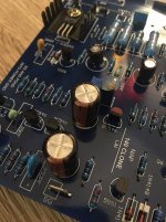
So I received a NAP-140 kit off eBay yesterday - I haven't received schematic/instructions etc, which seems to be the norm for these kits, so I'm chasing up the seller - but I did notice that the boards differ slightly, in that the cap closest to SG is backwards on one. Additionally, (what looks like) a half-watt resistor is out of place with it's 3 nearby 1 watt resistors, relative to the other board. Pics attached.
The seller apologised and said he'd kick the manufacturer up the rear, but I'm going to try and repair the board anyway, but has anyone else received a dodgy board and fixed it, or has a working one in action and can verify the proper position/alignment? Just a little nervous about trusting the silkscreen, considering the images I've seen of these boards online contradict the silkscreen anyway (it indicates the two caps near SG should be facing each other with respect to their negative terminals, rather than facing the same direction).
The seller apologised and said he'd kick the manufacturer up the rear, but I'm going to try and repair the board anyway, but has anyone else received a dodgy board and fixed it, or has a working one in action and can verify the proper position/alignment? Just a little nervous about trusting the silkscreen, considering the images I've seen of these boards online contradict the silkscreen anyway (it indicates the two caps near SG should be facing each other with respect to their negative terminals, rather than facing the same direction).
Attachments

Last edited:
What's your reference for the orientation of that input cap marked C5? Certainly, what you have is wrong in comparison to the tantalum caps used in the original NAP design and different to other clones but the orientation can be quite arbitrary because the voltage across the cap is usually too small to matter - it's only in the order of mV and insufficient to polarize the cap anyway. That's not a good situation either way but it works OK despite a reduced life for the electrolytic. It should really be a NP type cap. such as Nichicon ES but watch out for fakes.
On a "positive" note, it's good to see the original MJE243/253 drivers fitted. They do an excellent job with the original and the various clone output transistors that I and others have listened to.
On a "positive" note, it's good to see the original MJE243/253 drivers fitted. They do an excellent job with the original and the various clone output transistors that I and others have listened to.
Attachments
Last edited:
Thanks for the reply, and for the schematic, much appreciated! Good to know about the transistors as well.
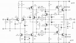
So would you suggest replacing the wayward capacitor with an NP cap? Any thoughts regarding the resistors? From what I can gather from the schematic (I'm still pretty green when it comes to schematics and reading them properly etc), the silkscreen is actually correct and shows that group of 4 resistors as 0.22r/0.22r/8.2r/0.22r - what would the consequences be of those being in the wrong place?
So would you suggest replacing the wayward capacitor with an NP cap? Any thoughts regarding the resistors? From what I can gather from the schematic (I'm still pretty green when it comes to schematics and reading them properly etc), the silkscreen is actually correct and shows that group of 4 resistors as 0.22r/0.22r/8.2r/0.22r - what would the consequences be of those being in the wrong place?
If you are going to replace the caps, replace both C5 and the more critical C6.
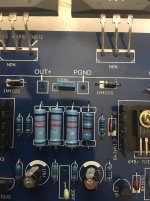
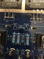
The boards I have in front of me are marked NAP 140C LJM and your 4th (last) pic shows the 8.2 ohm Zobel resistor position as it appears on my boards, 3rd in line from the left. I can only guess that the 3rd pic shows the resistor in the wrong position.
However, it only takes seconds to turn the board over and with schematic in view, note that all the 4 large resistors have a common connection one end but only the smaller 8.2 ohm resistor is connected at the other end to that 220n cap (just above in the pic). As that most likely is not the case, the assembler needs another kick and you need a few mm. more solder.
Yes, it would be a problem if that Zobel network resistor was only O.22 ohms instead of 8.2 and conversely, if an emitter resistor or the output resistor was hiked up to 8.2 ohms. If not a lot of heat, smoke at least would issue.
Looks like we have the same (or similar) boards - mine were made by LJM as well.
Pardon my ignorance but I'm not sure how to identify C5/C6 - like I said, I'm quite new to reading schematics, is there a general rule regarding the numbering of components in a schematic? I understand the symbology of the components (C, R etc), but not how the numbering is allocated.
Pardon my ignorance but I'm not sure how to identify C5/C6 - like I said, I'm quite new to reading schematics, is there a general rule regarding the numbering of components in a schematic? I understand the symbology of the components (C, R etc), but not how the numbering is allocated.
Sorry, it's printed on my boards which are rev.C and obviously different if you can't read it on your boards. They are the same 2 electrolytics featured in your first 2 pics.
Ahhh I see - that'd explain why I was so confused. Just to tap into your superior knowledge one more time, if you don't mind - what values would you recommend for the NP caps (or even tantalum capacitors as per the original? Or are they not suitable for this particular circuit)? The current electrolytics are 100uF (80v).
Not many would say superior about the little knowledge I have but 100uF for both caps seems like the result of quantity purchasing of a common value to get a low price. It's not a disaster but it should go like this:
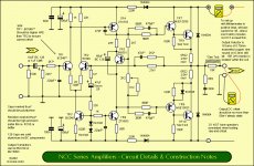
The caps each form an RC filter with an associated resistor and the first, with the 22k resistor, forms the input filter that determines the amplifier's lower frequency limit, while the second or feedback cap and 1k resistor, sets the lower limit of the feedback. Some lower limit is needed to prevent DC and power disturbances being amplified and preserve stability as the amplifier gain keeps increasing as it drops all the way down to 0Hz.
The input frequency roll-off has to be low, ≤20Hz, which is well below audible but you don't need to make it a subwoofer amplifier. This is done by the first or input cap which should only be a 10uF cap, not 100uF at the input. A larger value like 15-22uF might still be OK but 100uF is overkill and bad form. The second cap, further away in the pics, was originally a 68uF cap as you can see on the schematic but here you need a cap that sets a significantly lower frequency than at the input, so as to maintain feedback under all circumstances. 100uF or so is no problem there as long as price and space on the PCB is acceptable. Use minimum 16-25V or even higher voltage ratings for these, even though the voltages there are quite low.
The story of the boards I have, is that their owner wants special wet tantulum type caps fitted, and I'm waiting on them. They're also fitted with 100uF caps, "NRWA" branded. Ebay type kits are certainly cheap but you soon wise up to parts quality matters which are out of the hands of kit and board designers like LJM and over to the assemblers who either are traders too or just sell to them. Some shops do their own kits and assembly with better components but you can't always tell. 😕.
Last edited:
Would you use a film capacitor in place of an electrolytic in this case? I've been poking around a Naim mod guide and the author was gushing about how much of a huge improvement it was to swap out the tants with film caps (evox MMKs). I'm keen to give this a try with 47uF polyester film caps.
*Rant warning*
People who gush about vast improvements from changing parts types probably don't realise that TAG tantalums deteriorate due to various external influences and require replacement after some years - usually sooner than most electrolytic caps which can also die in shorter times than quoted in their failure time specs if mounted in hot positions and used in warm environments. It's not like Naim rose to its revered status without them or a brand new A$3,800 NAP 200 amplifier can be dramatically improved in a "night and day" change, is it? 🙄
It's true that top grade polypropylene film/foil construction (FKP) or even metalized film (MKP) types give lower audio distortion than say, metalized polyester film types (MKT), but I'd say that a lot of people just parroting the facts show a naivety in their understanding of what it means for their project and that they could probably get the results they crow about (and better) in other ways too.
Often, black/white listening results are down to cheese/chalk comparisons. In terms of subjective sound, I managed a few times with MKT caps, to reduce noise and apparent distortion on amps fitted with massive PP caps. One owner refused to accept there was anything wrong with his mods and parts but grudgingly agreed that the way it now sounded was better. The problem was in adopting "audio as religion" which is for those who really have no clue - just read the forum posts and buy the bits suggested by others in the same boat. Like sales pitch, the smoothest argument presentation and hyporbole is the always the right one, right? 🙄
The science, instrumentation and methodology needed to run credible tests isn't going to happen on the table at home with an Ebay kit but other changes in wiring dress, layout, shielding, optimizing parts values etc. are quite possible and probably will happen with tinkering about and following sensible advice from those like Rod Elliott who actually know something and have been through the hoops of learning and teaching audio electronics. It's a big site but if you haven't already spent a lot of time reading the ESP site, visit again and search the design topics: Elliott Sound Products - The Audio Pages (Main Index)
The film capacitor distortion differences by the way, are in the 3-6 decimal place and lower region so the amazing audible improvements cannot be down to changing film types. The sheer physical size of a PP film cap also brings on some counter-productive problems; first, they are quite expensive and only available up to limited practical sizes, then with their large size, they become an aerial for the power supply noise and spurious EMR flying around in the amplifier box. That's disastrous at the input end of a preamp or amplifier.
I find it hard to realise any benefit with with large film caps, short of mounting them away from amplifier boards or enclosing in a grounded metal tube or similar tricks. Where suitable, smaller types ≤ 1uF can make quite an improvement but I don't think you'll be able to measure or hear it unless as before, it's a no-brainer cheese /chalk comparison.
You can always hear dramatic improvements by swapping out old, deteriorated caps for new or changing the specification with overkill values etc. but that is another story, also laced with hyperbole.
Thank you for the illuminating rant - I hadn't even considered that the "epic improvements" would be due to old and crusty components being replaced with newer ones. A bit like changing a worn set of $100 tyres with a new set of $500 tyres and then assuming the improvement is in the more expensive brand rather that having tyres with tread on them again 😀 I'll set my hyperbole filter to "Wary" from now on.
I do have some new caps on the way to replace the 100uF ones (47uF film caps, seems like overkill now but oh well) and a nice 1/4" x 3" x 250mm copper bar arrived this morning which I plan to use as a heat spreader for the power transistors. I'd thought about mounting a heatsink to the vacant space on the copper but would it be necessary? Will the 4 SanKens generate enough heat that a 1kg lump of copper couldn't dissipate?
I also have a 14,100uF per rail power supply from an old Jaycar kit, but looking at other builds I'm unsure as to whether it's enough (but maybe you can blow away the "reality distortion field" here as well).
Thanks for the advice and insight - has been really valuable.
Hello guys , i have a question about tr7 and tr8. What kind of protection are those suppose to do? Most of the kits dont include them. Im curious if they are included in the Avondale kit/pcb
The copper bar is no problem, just an expensive way to do the job. The problem is losing the heat from the bar to the air around it and warming up the case and air inside so that the Vbe multiplier transistor, TR6, compensates the bias correctly and prevents thermal runaway. Naim products all use the aluminium case as the main heatsink and they don't generate much heat with their 30mA output stage bias current - about 5W for a stereo pair. When in an average room at comfortable domestic levels of only a few watts, it won't increase that much either, with the specified rail voltages. Regarding power supply, try to obtain a similar transformer to the specified 28-0-28V or 2 x 28VAC type. I get them as a special from Harbuch in Sydney who made them as a stock line, last I checked. Common 30V transformers may often be substituted for the power supply but this changes a few characteristics and stresses some parts for the worse, IMV. A 2 x 25VAC transformer would be a lesser problem, I think.
There are significant differences between the kits and the original design, before you even assemble. These are mostly to reduce parts costs where some are obsolete or not made in China. Mostly, this isn't a huge problem but key parts like the VAS transistors, ZTX653/753, do make a significant difference to sound quality because they are very different to the normal type of semi specified. This and almost all clone issues have been covered several times over years in the big, similar titled thread. Read at least some of it, where it is still on-topic. You'll find Ruwe's posts most useful in getting clones running and making decent sound.
http://www.diyaudio.com/forums/solid-state/112453-nap-140-clone-amp-kit-ebay.html
I think that if you are building a clone of a NAP series amplifier and not somthing derivative, there's no point trying to build one that is wrong in more important areas than caps, to start with.
Caps are always focused on by new folk because they are big, simple parts, easy to understand and buy. They make the big differences to old gear that people like to hear or imagine. Every tinkerer website jumps straight to caps and you should note if your you are reading the acoustica.org pages which date back quite some years now, the pics and topic there, are about the original Naim products, not the clone kits and as said, they aren't the same animal. The remaining kits now, are actually based on the boards used in NAP135 or NAP250 which is bridged mode, using 4 amplifiers for stereo which run on regulated 40V rails with the parts specified. NAP 140 is a lesser and simpler beast with unregulated 34V rails and a few minor adjustments to suit those voltages. It is often said to be the best sounding early model, despite the modest proportions.
For long term listening satisfaction, be careful with design and parts changes. Some impressive changes prove to be more drama than sound quality benefit over time, where you begin to notice annoying or fatiguing sound effects, evidenced by an urge to keep modding that often ends in binning or relegation to the closet. I have several friends who have done this all before and given up their dream of being a mod. king when the bills began to mount up and the sound quality became lost in confused ideas from off-handed suggestions, anecdotes and BS. A faithful or close clone build can sound absolutely great though - in the characteristic Naim, flat-earth and P.R.T. style. However, building in the Avondale NCC200 style can improve on that for more recent dabblers in kit audio who probably have never listened to a Naim system.
Hi asuslover, TR7 &8 form what are called VI limiters, often villified as screwing up the sound but used at normal domestic levels they have no effect that I can pick or complain about. There will always be folk who can hear anything they are told about, though.
Constructors follow the dire warnings and just omit them. Some kit suppliers ignore them and just make the smaller board. Naim still keep them for safety reasons because no relay or other current limiting protection device is used. Folks still are happy with Naim sound and not having the hassles of relays or fuses though. You can build a full board any way you like and just replace the shorted transistors as they occur but you couldn't sell an unprotected amp to the public like that.
Constructors follow the dire warnings and just omit them. Some kit suppliers ignore them and just make the smaller board. Naim still keep them for safety reasons because no relay or other current limiting protection device is used. Folks still are happy with Naim sound and not having the hassles of relays or fuses though. You can build a full board any way you like and just replace the shorted transistors as they occur but you couldn't sell an unprotected amp to the public like that.
- Status
- Not open for further replies.
- Home
- Amplifiers
- Solid State
- NAP-140 off eBay, component back to front.