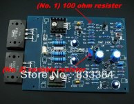
The (No1. labeled) 100ohm resister in the attached photo failed immediately on power up, red hot and smoked, I immediately cut power to it. I tested the board by its self and kept the other unhooked in case of this result. I would have it for comparison to find the effected components which as of now I do not think there are others? If this sounds unlikely to you please advice. Below are listed the things I did and didn’t do before power was applied.
1. The recommended voltage is 40vdc I used 44.5vdc I had concern with this but after asking got no do not do that’s, and a couple 4 volts should make no difference so I went for it. I checked, double checked and redouble checked the resisters for value before assembly and do not think it was a resister issue, but I could have missed one.
2. I did not do anything with the variable resistor (No.2) on the board; it was soldered in place as it came from the kit.
3. I did not ground the dc circuit to the chassis at any point, Ac was grounded at the entry to the enclosure. Ac passes thru a soft start circuit to the transformer to the power supply where I had 44.5vdc on exit, and polarity was correct to the amp board.
4. There was no load connected to the speaker out side of the amp board.
5. If over voltage is suspect what do you recommend as a method of reduction, I would prefer not to unwind the transformer but have no problem doing that if that is the best method. I did find one 100 ohm resister in my limited parts collection, it is larger physically than the one blown but of same value, to chicken to try it again with out advice. If other information would be helpful I will supply what I know as fact.
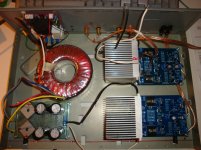
6. P/S this is my intended layout of the components minus speaker protection that's under construction, excuse the wiring it is for test before final assembly. Thanks.
1. The recommended voltage is 40vdc I used 44.5vdc I had concern with this but after asking got no do not do that’s, and a couple 4 volts should make no difference so I went for it. I checked, double checked and redouble checked the resisters for value before assembly and do not think it was a resister issue, but I could have missed one.
2. I did not do anything with the variable resistor (No.2) on the board; it was soldered in place as it came from the kit.
3. I did not ground the dc circuit to the chassis at any point, Ac was grounded at the entry to the enclosure. Ac passes thru a soft start circuit to the transformer to the power supply where I had 44.5vdc on exit, and polarity was correct to the amp board.
4. There was no load connected to the speaker out side of the amp board.
5. If over voltage is suspect what do you recommend as a method of reduction, I would prefer not to unwind the transformer but have no problem doing that if that is the best method. I did find one 100 ohm resister in my limited parts collection, it is larger physically than the one blown but of same value, to chicken to try it again with out advice. If other information would be helpful I will supply what I know as fact.
6. P/S this is my intended layout of the components minus speaker protection that's under construction, excuse the wiring it is for test before final assembly. Thanks.
Attachments
YOU have missed the most important thing, as i understand it is the current limiting device on the mains(bulb or HighValue resistor) or in the Amplifiers power supply rails (~100R resistors). Do not ever power circuits without these techniques, it is important to understand !!! It saves a lot TIME and money.
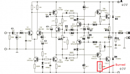
The resistor that burned connects output NPN base and driver collector to negative rail.
I attached a picture, there must been excessive current draw in that area. Wait now for smart guy to explain what really happend👍
The resistor that burned connects output NPN base and driver collector to negative rail.
I attached a picture, there must been excessive current draw in that area. Wait now for smart guy to explain what really happend👍
Attachments
With supply voltages 10-20% high, bias currents in the input stage, VAS and the output stage drivers will be high too, so heat is going to build up fast. You won't be doing the amplifier any favours by using higher voltage than the regulated 40V intended either (they are really based on NAP 250 design modules).
Often, a ready-assembled board will have been adjusted for correct output stage bias at the assembly point, but that depends on the supplier. It's not written anywhere, so the proper way to set up an amplifier is to use a bulb limiter and adjust the current to minimum and make sure you are monitoring the current through one of the 0.22 ohm output transistor "emitter" resistors by checking the voltage across it, so it's no more than 5 mV initially. Perhaps the driver bias was too high for that small resistor but a half-watt resistor should still be OK.
That should keep things cool as long as the bulb is only just lit, when you can remove the bulb limiter and set the final bias adjustment to 7.5 - 9mV after a warm up period. There is no thermal coupling to the bias control transistor, apart from the air in the case, so this takes time to stabilize!
As we find, the instructions for these ultra-cheap kits are just a schematic (maybe) and nothing, so you need to know all about amplifiers or check the many threads on amplifier set-up first.
YOU have missed the most important thing, as i understand it is the current limiting device on the mains(bulb or HighValue resistor) or in the Amplifiers power supply rails (~100R resistors). Do not ever power circuits without these techniques, it is important to understand !!! It saves a lot TIME and money.
The resistor that burned connects output NPN base and driver collector to negative rail.
I attached a picture, there must been excessive current draw in that area. Wait now for smart guy to explain what really happend👍
You are 100% correct rensli, I have been very patient and meticulous through out this project but the quest for results finally got the best of me. It is now time to build the bulb tester that I should have built in the first place, I will have future use for it as I do believe I am now HOOKED. P/S your drawing is helpful in pointing out the resister and it's relationship to the circuit.
Last edited:
With supply voltages 10-20% high, bias currents in the input stage, VAS and the output stage drivers will be high too, so heat is going to build up fast. You won't be doing the amplifier any favours by using higher voltage than the regulated 40V intended either (they are really based on NAP 250 design modules).
Often, a ready-assembled board will have been adjusted for correct output stage bias at the assembly point, but that depends on the supplier. It's not written anywhere, so the proper way to set up an amplifier is to use a bulb limiter and adjust the current to minimum and make sure you are monitoring the current through one of the 0.22 ohm output transistor "emitter" resistors by checking the voltage across it, so it's no more than 5 mV initially. Perhaps the driver bias was too high for that small resistor but a half-watt resistor should still be OK.
That should keep things cool as long as the bulb is only just lit, when you can remove the bulb limiter and set the final bias adjustment to 7.5 - 9mV after a warm up period. There is no thermal coupling to the bias control transistor, apart from the air in the case, so this takes time to stabilize!
As we find, the instructions for these ultra-cheap kits are just a schematic (maybe) and nothing, so you need to know all about amplifiers or check the many threads on amplifier set-up first.
Ian thanks for the voltages for the bias settings. I have had no luck as to locating any specifics concerning the matter. Can I assume that setting a maximum resistance on the transistors would be a appropriate place to start to be on the safe side? Also the 7.5 - 9mV as a final bias setting, Is this determined by ear in relation to the amp performance, more on that later. And yes I am putting the breaks on the show to build a bulb limiter, anticipation got the best of me and I paid the price, with any luck that price was a resistor.
Less
There are several UK forums and websites that take cloning and modding Naim products very seriously. Here is the most reliable one I know of that details setting the bias current correctly for all the old Naim amps which share the same topology, design and most parts even. As it is a Quasi-complementary design, increasing the bias to abitrary high levels like we do with the usual complementary class AB designs you see on this forum, doesn't improve anything, not even the sound quality. It just makes bad things happen sooner. Note the many other models there and the NAP250 schematic shown on the site.
The following procedure by Neil McBride is the best IMO, quoted from the page shown below. Alternatives are also described, but this is going to be correct whilst others are more prone to errors. Make sure no input nor speakers are connected to the poweramp.....
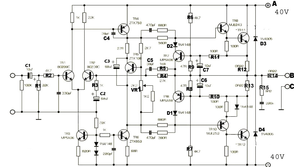
Neil mcbride says "To set the biasing of the amp, do this: initially before you power-up for the first time, set the 2K trimmer [VR1] on the amp board to about the mid point. When the whole thing is up and running, you want to set the bias by measuring the voltage across [R12 in fig1] (the 0R22 resistor that is attached to the 'positive side' [of the] output device emitter). With no input, twiddle the trimmer until you get about at least 2.2 mV (ie, 10 mA bias current). The desired setting is arguable. I find about 20mA (4.4 mV) is about adequate, although I tend to run at 30 mA to be sure. Naim also use about 30 mA with their devices. There's room for experimentation. If you go too high the amps risk thermal runaway, but if heatsinking is adequate then 30 mA is worth using."
Have a look at this page about bias and distortion, measured on a Nait 2. The same principles apply to all Naim power amps. Undoubtedly the correct way to do it is to set bias for minimum distortion, but you really need a scope amonst other equipment to do this. Fortunately the exact setting is pretty forgiving in the NAP design.
Modifying Naim Audio power amplifiers
Note that Neil's settings are more conservative that the maximum values I indicated and I guess he has a lot more experience and info to call upon. I have tried them but don't see any need, so stick with Neil's advice.
There are 3 x 0.22R 2W resistors there, so check you have the right ones to measure the voltage across. Personally, I measure across both resistors in series, the upper one connected to TR11 emitter, and the lower attached to TR12 collector - that's R12 & 13 as shown on Acoustica's marked NAP250 schematic, below. R14 is unrelated.
I simply clip the probes (don't slip and blow everything with just the probes) on the those appropriate transistor legs and read the voltage as twice that specified, so 11mV is read where 5.5 mV is specified etc. With cheap DMMs, that will be more accurate, too - a piece of cake, really 🙂
The following procedure by Neil McBride is the best IMO, quoted from the page shown below. Alternatives are also described, but this is going to be correct whilst others are more prone to errors. Make sure no input nor speakers are connected to the poweramp.....
Neil mcbride says "To set the biasing of the amp, do this: initially before you power-up for the first time, set the 2K trimmer [VR1] on the amp board to about the mid point. When the whole thing is up and running, you want to set the bias by measuring the voltage across [R12 in fig1] (the 0R22 resistor that is attached to the 'positive side' [of the] output device emitter). With no input, twiddle the trimmer until you get about at least 2.2 mV (ie, 10 mA bias current). The desired setting is arguable. I find about 20mA (4.4 mV) is about adequate, although I tend to run at 30 mA to be sure. Naim also use about 30 mA with their devices. There's room for experimentation. If you go too high the amps risk thermal runaway, but if heatsinking is adequate then 30 mA is worth using."
Have a look at this page about bias and distortion, measured on a Nait 2. The same principles apply to all Naim power amps. Undoubtedly the correct way to do it is to set bias for minimum distortion, but you really need a scope amonst other equipment to do this. Fortunately the exact setting is pretty forgiving in the NAP design.
Modifying Naim Audio power amplifiers
Note that Neil's settings are more conservative that the maximum values I indicated and I guess he has a lot more experience and info to call upon. I have tried them but don't see any need, so stick with Neil's advice.
There are 3 x 0.22R 2W resistors there, so check you have the right ones to measure the voltage across. Personally, I measure across both resistors in series, the upper one connected to TR11 emitter, and the lower attached to TR12 collector - that's R12 & 13 as shown on Acoustica's marked NAP250 schematic, below. R14 is unrelated.
I simply clip the probes (don't slip and blow everything with just the probes) on the those appropriate transistor legs and read the voltage as twice that specified, so 11mV is read where 5.5 mV is specified etc. With cheap DMMs, that will be more accurate, too - a piece of cake, really 🙂
The missing link from "have a look at this page about bias and distortion..." in the italicised text above , for interest: Naim, NAPs, Naits, distortion and bias-current settings
Are you sure all the transistors are in the right position. I remember some chinese pcb's have wrong pinout on silkscreen. This is a simple circuit and should not make big problems. I fully agree is important to use a current limiter (bulb) or low power resistor (i use 10r 0.25w for the first start of an amp)
Also on the Naim clone thread Ruwe in the post #241 has a very nice advice how to start a Naim clone without power transistors connected:
Quote:
9.Measure the voltage across the 100-ohm resistor between the base and emitter of the top output transistor (Remember, you still don't have the output transistors on the boards). Turn the trimmer and set this voltage to be small: 0.25V-0.30V, or less if possible, is fine. Now you can safely connect the power transistors and they won't have dangerous currents through them. They shouldn't have current at all in this situation.
10.Turn slowly the trimmer with the power transistors in place until you see about 5.5-7 mV across the output resistors (in the output transistors' emitters)
- Status
- Not open for further replies.
- Home
- Amplifiers
- Solid State
- NAP-140 Clone kit test & failure