D
Deleted member 543346
Bought this unit as defective , as the last tech was not able to fix the amp.
Managed to make it out of protect , and adjusted bias first on left and after the right side.
Tested the amp and got sound both channels.
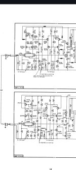
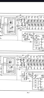
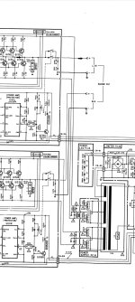
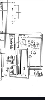
Now the servicemanual only refer to VR11L and VR11R , but i also have VR12L and VR12R that i cannot see described in adjustment info nor in the schematics.
VR12 is connected betrween R113 and D105.
When i first biased it i got up to around 20mv , and when i decided to do final bias adjust i connected DW to both left and right channel.
Will add more info
Now i had about 2 mv on left , but still had about 20mv on right channel.
When adjusting the left side , the right side bias drop in mv?
Managed to make it out of protect , and adjusted bias first on left and after the right side.
Tested the amp and got sound both channels.
Now the servicemanual only refer to VR11L and VR11R , but i also have VR12L and VR12R that i cannot see described in adjustment info nor in the schematics.
VR12 is connected betrween R113 and D105.
When i first biased it i got up to around 20mv , and when i decided to do final bias adjust i connected DW to both left and right channel.
Will add more info
Now i had about 2 mv on left , but still had about 20mv on right channel.
When adjusting the left side , the right side bias drop in mv?
Attachments
-
 Screenshot_2024-01-23-17-14-19-57_e2d5b3f32b79de1d45acd1fad96fbb0f.jpg244.8 KB · Views: 86
 -
 Screenshot_2024-01-23-17-14-46-69_e2d5b3f32b79de1d45acd1fad96fbb0f.jpg202.4 KB · Views: 90
 -
 Screenshot_2024-01-23-17-15-04-14_e2d5b3f32b79de1d45acd1fad96fbb0f.jpg246.8 KB · Views: 79
 -
 Screenshot_2024-01-23-17-15-14-07_e2d5b3f32b79de1d45acd1fad96fbb0f.jpg238.8 KB · Views: 76
 -
 Screenshot_2024-01-23-17-15-25-20_e2d5b3f32b79de1d45acd1fad96fbb0f.jpg208.6 KB · Views: 72
 -
 Screenshot_2024-01-23-19-16-53-29_e2d5b3f32b79de1d45acd1fad96fbb0f.jpg153.8 KB · Views: 86
The current through VR11 is controlled by Q139 to keep the voltage across it equal to 0.7V. This sets the current through the other resistors in series with VR11, thus controlling the bias voltage.
It looks like the VR12 is controlling the VAS current. The schematic says the voltages about R110 should measure +2V, -2V. I would tune VR12 to achieve this result, then tune VR11 to achieve the desired bias.
Correct me if I'm wrong about calling that part of the circuit VAS, as I am not so familiar with this architecture. However, I'm sure that the VR12 will control the current through R110.