I visually verified that it doesn't look like I ever touched the solder joints of Q111. Pulling those, I see:
Q111L:
BJT-PNP
hFE=143
Ic=1.3mA
Vbe=653mV
Q111R:
BJT-PNP
hFE=126
Ic=1.2mA
Vbe=654mV
Q111L:
BJT-PNP
hFE=143
Ic=1.3mA
Vbe=653mV
Q111R:
BJT-PNP
hFE=126
Ic=1.2mA
Vbe=654mV
Okay so Q111 seems comparable with your measurements of Q110 back in post #98. So they should be okay.
I'm assuming the voltage readings at the bases of Q108/109 is the same as before replacing q102/103?
While its powered up check to make sure you still have 3V across ZD12 which is attached to the emitter of Q108/109 and to the bases of Q110/111.
I cannot remember if you measured it or not, but what is the voltage on the collector of Q112 now? I know it was replaced early in the process but I'm still suspicious of Q112.
So you've checked basically every active component on the front end of this circuit and found a few dead transistors. We should probably look more closely at the passive components now.
Also with the amp powered down and fully discharged measure the resistance across C103. This is a small 15pf cap attached to the feedback side of Q101. Also measure across C106 and make sure it is not showing up as shorted too. I do not think C106 would cause this issue but it needs to be checked.
One thing to look at here. Most of the small electrolytic caps in the front end of this circuit are low voltage types. If full neg rail was on the feedback side of Q101 then C104 is only a 16V rated bipolar so it would have greatly exceeded the rated voltage and may have been damaged. I do not think that this cap is shorted but it worth measuring the resistance on this cap to ground while powered down too.
You can test some of these caps in-circuit with your transistor tester too. C104 should give a good measurement as its tied to ground. C103 will have to at least have one leg lifted to get a solid measurement from it. But at least measure across them to see if any show shorted.
Just make sure that the electrolytic caps are fully discharged before testing them.
Last edited:
One other thing after looking back at the this thread. Make certain that you still have the input signal pins (RCA's) solidly connected to ground. I'd fashion a temporary wire back to the star ground plate on the main caps just to ensure a rock solid ground connection there. It could be that your chassis connection although clean may not have a great path back to star ground.
That's the point that you got close to the correct voltages on the bases of Q116/117.
The input LTP was still buggered up with blown Q104's but for some reason right after grounding those input signal pins the Q116/117 voltages came into line.
That's the point that you got close to the correct voltages on the bases of Q116/117.
The input LTP was still buggered up with blown Q104's but for some reason right after grounding those input signal pins the Q116/117 voltages came into line.
OK, with the Q111s reinstalled and before powering up, and while I have the boards on the bench, I'll measure the caps. Measuring in-circuit for shorts first:
C103L: 3.556M
C103R: 3.561M
C104L: 23M
C104R: 22M
C105L: 23M
C105R: 22M
C106L: 2.61k
C106R: 2.62k
Don't caps sometimes fail open? If that were the case, I might not see a problem without putting it in the transistor tester.
Here are my results with the transistor tester, again in-circuit:
C104L:
225.2uF ESR=.52ohms Vlos=1.7%
C104R:
223.6uF ESR=.52ohms Vloss 1.9%
C105L:
225.6uF ESR=.51ohm Vloss=1.7%
C105R:
223.6uF ESR=.52ohms Vloss 1.9%
The same results make sense since those caps are in parallel. So it looks like those are intact. I don't have time today to pull a leg of C103. Do you think I should do that before I proceed?
Most of the caps I've ever seen that failed due to an overload would measure shorted or very low ohms, like 100 ohms with a DMM. Your tester will show the ESR which should be relatively low like typically < 2 ohm for a small to medium sized electro.
The only really low one is C106 and its low because its measuring in parallel across the resistance of the bias network. So nothing in those measurements stand out as out of place to me.
I think you'll be fine with leaving C103 in-circuit, its measuring relatively high with the DMM as I expected it would.
If after this next power test nothing stands out then I may suggest another isolation procedure to operate the front end LTP by itself. I'll explain after you do the next power test.
I forgot to mention.
One thing about using a DMM to test the resistance of a capacitor is that a good capacitor will charge up and the resistance will climb as it does so. Typically it should wind up well into the Meg ohm range. Thats a good indication of whether or not the capacitor is holding a charge, short the caps leads and then put your DMM on resistance the connect your test leads to the cap and see if the resistance climbs.
One thing about using a DMM to test the resistance of a capacitor is that a good capacitor will charge up and the resistance will climb as it does so. Typically it should wind up well into the Meg ohm range. Thats a good indication of whether or not the capacitor is holding a charge, short the caps leads and then put your DMM on resistance the connect your test leads to the cap and see if the resistance climbs.
So I'll go ahead and post the next test for you to perform if the bases of Q108/109 still measure highly skewed from each other upon powering it up this next time with the ground wire mod I suggested earlier. I'm fairly sure they'll still measure off quite a bit.
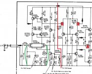
I posted a picture for you for this mod. You'll be isolating everything left of the red line in this test from the rest of the circuit to the right of the red line. Remove Q108 & Q109 from the board, then lift one side of R120 to open the feedback circuit. Now add jumpers where the green lines are at. So you'll be shorting the two input jfet gates to ground, this will keep them on when you power up again. Now you're ready to power up. The input LTP should now idle with fairly even current between the two legs of R103/104 flowing through the two sides of that input diff circuit.
Measure the voltages that are going out to the now vacant Q108 & Q109 base. Are they balanced now or a lot closer than they were before? They may still not be perfectly balanced but they should be a lot closer. If they're not a lot closer then there's problems in this section of the circuit.
Let me know if you have any questions.
BTW if anybody else is following this thread and see's something that they would recommend testing please speak up!
Attachments
Ok, I added a ground wire to the main cap star ground and verified with a meter that my RCA +/- are grounded to that. Just a reminder for those following along that Q116-119 are removed.
Q108L base: 64.6v
Q108R base: 64.85v
Q109L base: 74.6v
Q109R base: 74.6v
So that looks about the same.
ZD12L R109 side: 65.50v
ZD12L R111 side: 62.68v
ZD12R R109 side: 65.57v
ZD12R R111 side: 62.35v
Still getting about a 3v drop.
Unless there's anything else you want me to test in this configuration, I can proceed to put the amp in the configuration you list in your latest post. I probably won't get to it until tomorrow though.
Yes go ahead and perform the test I outlined in my previous post with the image attached.
If the voltages are still way out between the two legs of the LTP (measured across the bases of Q108/109) then I'm suspecting that Q101 is bad.
If the voltages are still way out between the two legs of the LTP (measured across the bases of Q108/109) then I'm suspecting that Q101 is bad.
I attempted to set both boards up in the manner you described. When I plugged them in and powered the amp on, I got some smoke from the left channel. R103 and R104 were particularly hot. Despite checking with my DMM, I must have messed up the shorting wires on Q101. I'll check where the short is when I get a chance. But yeah, that's a major bummer.
So for now, I removed the left channel and will just measure the Q108R and Q109R bases to chassis:
Q108R base: 78.5v
Q109R base: 78.0v
So, a lot closer than they were before.
So for now, I removed the left channel and will just measure the Q108R and Q109R bases to chassis:
Q108R base: 78.5v
Q109R base: 78.0v
So, a lot closer than they were before.
Yeah that sucks on the left channel hopefully its not too serious. Be careful when you power the left channel back up. I'd watch the voltage drop across R103 or 104 at power up. If its really high, like more than a couple of volts, then immediately shut the amp off. Some thing may have shorted in that part of the circuit and more damage will ensue.
Those Q108R/109R voltage measurements are a lot better. I would've liked to have seen them even closer because even a half volt at that point in the circuit is a lot of imbalance. Without any degeneration resistors to help on the output of the Q101 jfets even small differences between the devices can cause imbalance. But the second stage should be able to adjust for that small voltage difference I would think.
One other thing that I notice here is that the 108R base is actually higher than 109 in this test. In your prior tests Q108 was 10V lower. I would actually replace Q111/110 at this point. I know that they're measuring good with the tester, but something is bad in this part of the circuit when its loaded with full rail voltage so something is breaking down under higher voltages. I believe the KSA1381 is a match for those, the KSA1220 would probably also work as they're just a voltage follower. I need to look a the data sheets of them to verify that though.
You're kind of in a shotgun mode now. Things are measuring good and the tests of the right channel input LTP appears good. So we need to move to the next stage in the amp. Let me verify that those transistors are whats needed for Q111/110.
The KSA1381 is going to be the closest replacement for Q110/Q111. The only thing is of course its the larger TO126 style package. So as long as the KSA1381 will fit in that location I'd use it.
The KSA1013 is the same type of package but the spec's for fT are a bit lower than the SA1370 and the Pc is also a bit lower at 900mW.
Did you find what caused the overheating on the left channel input LTP?
The KSA1013 is the same type of package but the spec's for fT are a bit lower than the SA1370 and the Pc is also a bit lower at 900mW.
Did you find what caused the overheating on the left channel input LTP?
You know I just went back and looked at the measurements you took the other day across ZD12 and compared them to your prior measurements you posted on the image of the schematic.
ZD12L R109 side: 65.50v
ZD12L R111 side: 62.68v
ZD12R R109 side: 65.57v
ZD12R R111 side: 62.35v
Those measurements are vastly different than your prior measurements that you recorded in the picture you posted much earlier. You are dropping around 14V across R109. Thats a LOT of current being drawn through that circuit. Like 186mA which is a huge problem. There should only be 8mA through that resistor.
I would pull Q112 and remeasure it and measure the Q108/109's that you pulled out of circuit for the last test.
I see what you mean about ZD12. I haven't found the source of the left channel short. I did a bunch of measurements and couldn't find a short from the rail to ground. So I'm not sure what's up there. The resistors that got hot definitely need to be replaced, and I'm guessing Q103 and Q102 at least as well.
I pulled Q112 from both channels and measured:
Q112L
BJT-NPN
hFE=81
Ic=0.76mA
Vbe=636mV
Q112R
BJT-NPN
hFE=80
Ic=0.75mA
Vbe=637mV
I compared the Q112 measurements to a new KSC3503 and they are quite similar.
Q108L
BJT-PNP
hFE=415
Ic=3.8mA
Vbe=653mV
Q108R
BJT-PNP
hFE=406
Ic=3.7mA
Vbe=652mV
Q109L
BJT-PNP
hFE=318
Ic=2.9mA
Vbe=649mV
Q109R
BJT-PNP
hFE=325
Ic=3.0mA
Vbe=650mV
I can place an order for the KSA1381 along with the resistors. I'm pretty sure I can fit the TO-126 in that footprint since I was able to use the KSC3503s earlier. What do you think, is there anything else I should measure before I place the order?
You measured the voltage drop early in the process across the 4148 diodes, but I'd go ahead and order 10 of them too. Recheck all of the resistors in the input and second stage just to make sure something isn't out of spec now with the high currents that were experienced. Check R105 for sure.
One thing I noticed looking at your numbers for Q108/109. It looks like the Q108's are matched to each other and the Q109's are matched to each other.
If that is the case this is wrong. The Q108/109 pair in each channel should be matched to each other. We don't care if anything is matched from the left to right channel.
So just to be clear, Q102L & Q103L should match each other as close as possible for Vbe & hFE if possible. Also Q108L & Q109L should also match each other for the same parameters. The same is also true for the right channel versions of the same transistor pairs but they do not need to match anything in the opposite (L) channel.
So as an example you could have Vbe/hFE of 630mV/405 for both Q108L/Q109L and then in the opposite channel have Vbe/hFE of 605mV/445 for the Q108R/109R pair and this would be completely fine.
Sorry if I wasn't clear on this before.
I'm going to drop you a PM too about some other parts.
No, you were clear and I was pretty sure I had matched them on a per-channel basis. However, you're right, it looks like I crossed channels. I will make sure to match them when they are reinstalled.
I'll order the 4148s as well, and will recheck the front end resistors before I order.
I'll order the 4148s as well, and will recheck the front end resistors before I order.
FYI, I found the reason my left channel was getting warm. I had shorted the wrong transistors, not Q101. Pretty stupid, but I think I was trying to work fast that day, which is usually the problem. So that means I had a short from Q104 collector and Q105 collector to ground. Which would also mean Q102 and Q103 collectors were shorted at the same time. I guess I should just pull those parts and test them, and probably will end up replacing them.
I haven't found any blown passives in that area of the input circuitry, but obviously I'm replacing the parts that got toasty.
I haven't found any blown passives in that area of the input circuitry, but obviously I'm replacing the parts that got toasty.
I pulled Q102-105 and tested them, and they appear intact, which is surprising given how much current must've been flowing through R103L and R104L.
Q102L:
BJT-PNP
hFE=402
Ic=3.7mA
Vbe=656mV
Q103L:
BJT-PNP
hFE=408
Ic=3.7mA
Vbe=655mV
Q104L:
BJT-NPN
hFE=369
Ic=3.4mA
Vbe=665mV
Q105L:
BJT-NPN
hFE=392
Ie=6.2mA
Vbe=683mV
I'll wait to place my digikey order until tonight in case there's anything else you think I should check.
Q102L:
BJT-PNP
hFE=402
Ic=3.7mA
Vbe=656mV
Q103L:
BJT-PNP
hFE=408
Ic=3.7mA
Vbe=655mV
Q104L:
BJT-NPN
hFE=369
Ic=3.4mA
Vbe=665mV
Q105L:
BJT-NPN
hFE=392
Ie=6.2mA
Vbe=683mV
I'll wait to place my digikey order until tonight in case there's anything else you think I should check.
Okay that makes sense so Q102/103 would have seen around 200mA I believe. They're only rated for 50mA max so I would replace them just to err on the side of caution. In fact I would go ahead and replace Q102/103/104/105. No reason to leave something in there that might be questionable especially when the replacement parts are readily available and cheap.
- Home
- Amplifiers
- Pass Labs
- Nakamichi PA-7II won't power on, limiter resistor blown