How did you pinpoint these?There were indeed leaky transistors, which showed their bad characteristics only under given circumstances.
@madis64, I apologize for the delayed response.
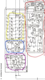
As previously mentioned, the device worked properly at lower voltages but was going into protection at higher voltages.
Since there was a high DC offset before the output relay, the issue was not within the protection circuit but within the audio circuitry itself. So, the protection circuit marked in red could be ruled out.
While the device was working properly at high currents and at a voltage around 30% lower than it was designed for + the input at the 2SA968 and its complementary transistor was off at the original voltage level. Therefore, the output stage and drivers, both marked in yellow and blue, could also be ruled out.
This left only the section marked in purple to be at fault.
There were basically only seven bipolar transistors and two FETs that could have been at fault. What I did was take the good side, short the audio input while leaving the output floating, measure the voltage at e, b, and c (referenced to ground) of those transistors, and compare them to the bad side. It was very easy to spot the bad transistors that way.
I guess you could also take all 9 transistors out and put them into a component tester to find the leaky transistors. However, because the PCB was already in bad shape and is unfortunately made out of paper (FR-2 ?), I did not want to expose it to any more heat than necessary. So, I measured the e, c, and b of the transistors and compared the results of the bad and good sides to spot the leaky transisors.
I would also like to know how others would have approached this issue.
Best regards from Germany.