If you are using Fets for the input differential pair, then you can easily
make it balanced. (Actually you can probably get away with it for bipolars
as well)
Check out the tutorial on this in the A75 amplifier parts 1 and 2 on the
PassDiy or First Watt article pages.
😎
make it balanced. (Actually you can probably get away with it for bipolars
as well)
Check out the tutorial on this in the A75 amplifier parts 1 and 2 on the
PassDiy or First Watt article pages.
😎
It's the "they can't hurt" part that I was concerned about. Without knowing if it was part of the original Stasis design, combined with not finding it in the other amp, is why I questioned it.
I was just trying to figure out if it was there to make the amp as stable as possible across the widest possible audience at perhaps a slight degradation of the sound vs running it a little more "risky" to get that extra margin of performance.
I would assume that Nak would have tended to lean on the ultra conservative side as they likely wanted the most reliable product possible.
As I mentioned, I don't have the design knowledge, so I didn't know how to interpret its purpose but was looking to eek out the best performance possible. Hence why I asked.
Thanks to all for the help.
Best regards,
Steve
Hello colleagues,
I will refresh a very old thread, I replaced all small capacitors in my pa7 and I noticed that what we put in place of the C105/C205 has a significant impact on the sound. The no longer produced Elna ROA RED that was there was sounds great, modern capacitors do not give such effects anymore. I tried the auricap XO which gave amazing space and detail but the sound seems a bit harsh. How your research with this system has ended? Thanks!
Hello olmaster,
I recently recapped the two VAS shunts and used 10uf/35v Elna Silmic II capacitors. Sound was improved, as the cerafine caps previously used were out of spec. This seemed to improve sound, I also set dc balance and idle current. It was running at around 150mv when I got it vs the 40mv.
I used this for over a week before getting brave and using two of the 470uf/25v bipolar Nichicon muse and two 4700pf/63v 1% wima film/foil caps in parallel to replace each of the large 10uF/200v mylar feedback capacitors. It would be quite easy to design a board for this. I also made sure to put the new electrolytic capacitors away from the output transistors
Next, I intend to buy a stock of NOS output transistors and redo transistor matching with a jig. Once this is done, I intend to bias it much higher into class A.
I still have yet to replace the small protection capacitors, but should do that at the same time as the output rematching.
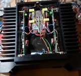
To continue my efforts, I replaced the entire protection circuit. The 47uf bipolar cap was replaced with a bipolar muse. The 10uF/100v bipolar was swapped to a Panasonic film (I noticed simular amps used a film cap here).
I installed new ohmite audio grade non-inductive 1% emitter resistors as well. This seems to have a positive effect on stability and sound.
I also added 4.7uF bypass caps to the main filters. These were already around and I had extra.
Overall, I'm very pleased with the results.
Amp is now around 50mv or so of idle current keeping perfectly stable.