Previously, I had measured all clocks and voltages as specified in the schematic. All clocks looked stable and were in frequency. Voltages were fine too. What is disturbing is that the with the old laser unit, I could see the laser but it was very dim. Not as bright as another Sony CD player that I observed today out of curiosity. It seems that U101 is driving the laser diode and I am wondering if it is a defective IC.
The new laser unit does not light up at all. It did not have a short but has a capacitor that I have not removed. It could be that the removal of the capacitor may do it but I am hesitant. Previously Mooly had suggested too that it not be removed.
The new laser unit does not light up at all. It did not have a short but has a capacitor that I have not removed. It could be that the removal of the capacitor may do it but I am hesitant. Previously Mooly had suggested too that it not be removed.
It would be very unlikely that this transport is shipped without shorted laser diode. Perhaps you didn't spot it. Is the capacitor you mention again not present on the older transport?
Try putting back the old transport and also try the experiment I suggested because the crystal may be ringing overtones.
Try putting back the old transport and also try the experiment I suggested because the crystal may be ringing overtones.
I am sure that there are no shorts, which surprised me too. On the other hand there are no caps on the old transport. Hence I thought that the cap on the new one may have to be removed. I have sent a email asking the vendor. Waiting to hear back.
As suggested, I am in the process of installing the old transport and check the crystals. I believe there are two crystals. One for the signal processor chip and the other for the uP.
As suggested, I am in the process of installing the old transport and check the crystals. I believe there are two crystals. One for the signal processor chip and the other for the uP.
It is difficult to suggest what to try next tbh. DVD and CD lasers are quite different, if you can detect the faint glow from the CD pickup then we have to assume that as its the second one fitted that it is OK.
The sequence of events is typically,
1/ Focus search performed (lens bobbing up and down)
2/ Only if focus is detected on a disc surface does the platter spin.
3/ The platter is 'kicked' to approximately a speed that will allow the servo to lock.
4/ Once the incoming RF is detected it is then compared in frequency to a crystal generated clock at which point the servo attempts to bring the two together... servo locked.
Is the platter motor OK ? DC motor ? does it spin freely. It could be worth isolating it and giving it a spin on a 9 volt battery for a few seconds.
My apologies for not detecting the tiny short that had to be removed on the new laser unit. I guess its my aging eyes!
Anyways, the symptoms are the same with the new laser unit as was seen with the old one.
I have checked the crystal frequencies and pinched it and see no difference.
The platter motor spins freely. don't see any issues with it.
U101 Pin 28 is the FOK output pin. This pin I suppose should go either high or low once focus is detected. (Mooly had pointed this out previously)This pin does not change state and is noisy. Given the fact that the laser unit has been replaced and voltages at various points associated with U101 as shown in the schematic are correct, it may be that U101 is defective. Any thoughts.
I imagine U101 is operational amplifier. Check if it is getting hot. However, if it drives the focus motor and you can see the lens bobbing up and down, it means it is OK.
U101 is CXA1018S. It is not getting hot.
U101 has a output FOK pin which should change state if focus is ok, I think. It never does, hence my suspicion. The FOK pin from here goes to CXA1082BS as well as the MPU. My thought is that if FOK is not detected by the the two ICs, the sequence of operation stops.
U101 has a output FOK pin which should change state if focus is ok, I think. It never does, hence my suspicion. The FOK pin from here goes to CXA1082BS as well as the MPU. My thought is that if FOK is not detected by the the two ICs, the sequence of operation stops.
You have done all the right things so far... and I'm afraid I've no easy suggestions left. Having got the same symptom with the original pickup and now two replacements (and we had to try those... and think the worse that the first new one could have been suspect) means you are moving into more difficult territory. Complex IC's like the CXA are always always way down the list of suspects in any fault like this. Only when everything else has been checked do you even begin to think of replacing them.
If I was faced this on the bench I would use a scope as a voltmeter and go around all the rails and all the pins on the servo and syscon IC's and look for anything obviously amiss such as an obvious wrong logic level (like a reset input) or some indeterminate state somewhere. Not easy but you can get lucky. Don't assume anything, scope every pin, even the ground... you never know.
If I was faced this on the bench I would use a scope as a voltmeter and go around all the rails and all the pins on the servo and syscon IC's and look for anything obviously amiss such as an obvious wrong logic level (like a reset input) or some indeterminate state somewhere. Not easy but you can get lucky. Don't assume anything, scope every pin, even the ground... you never know.
U101 is CXA1018S. It is not getting hot.
U101 has a output FOK pin which should change state if focus is ok, I think. It never does, hence my suspicion. The FOK pin from here goes to CXA1082BS as well as the MPU. My thought is that if FOK is not detected by the the two ICs, the sequence of operation stops.
CXA1081 is a bad IC. We replaced many in repair service.

Hello QSerraTico_Tico
Could you tell me more about the symptoms of a bad CXA1081S? Are they similar to what I am observing?
Just wanting to make sure before I replace it.
Could you tell me more about the symptoms of a bad CXA1081S? Are they similar to what I am observing?
Just wanting to make sure before I replace it.
Hello QSerraTico_Tico
Could you tell me more about the symptoms of a bad CXA1081S? Are they similar to what I am observing?
Just wanting to make sure before I replace it.
No signal output from IC, after laser already replaced.
Bad guy here is the Servo Signal Processor CXA1082BS, Just try apply some cooling spray on it, and you will see 🙂
Hello. I need help with a machine of this same model. The problem occurs mainly with non-original CDs, although it reads the toc correctly, during playback it skips track, repeats fragments or is lost when pressing the skip, with original CDs, the problem almost never happens. I do not have that kind of interface that the service manual suggests to carry out the adjustment but I deduce that some measurements can be done the same, I am measuring the RF signal and I notice that with original CDs it has greater amplitude, adjustment according to the manual the F.BIAS in order to obtain the greatest possible amplitude, so far, everything OK, but the EF BAL setting that should be left at 0V +/- 0.1V is not working well, I have a slightly negative voltage that when I try to bring it closer to 0V , the reader is lost. I have replaced the optic drive with a new one and the problem persists. An additional detail, to see if I can explain myself well, is that the amplitude of the RF signal increases and decreases its amplitude a little at the rate of rotation of the CD (let's say it compresses and expands about 100mV over an amplitude of 1Vpp), it is say in the beginning tracks the variation is fast and much slower in the tracks on the periphery of the CD
Hello.
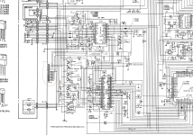
I add some information, tuning indications (partial) and test points about the circuit.
Videos of what the RF signal looks like
There is a video of the first track and the other one is about a track of the last ones.
TP1 - RF signal
TP5 - TE (E F BAL)
I add some information, tuning indications (partial) and test points about the circuit.
Videos of what the RF signal looks like
There is a video of the first track and the other one is about a track of the last ones.
TP1 - RF signal
TP5 - TE (E F BAL)
Attachments

Last edited:
How often do Sony servo IC chips fail?Bad guy here is the Servo Signal Processor CXA1082BS, Just try apply some cooling spray on it, and you will see 🙂
I'm currently restoring a Denon DCM-320 5-disc changer with a really unusual intermittent fault.
Sometimes it works perfectly.
Other times it spins up the disc, gets a perfect eye pattern, reads the TOC, but then enters an unstable condition where there is no movement of the sled, yet the disc is still rotating. When this fault occurs the RF signal eye-pattern drops to 50% amplitude and becomes very noisy. However, the RF signal & eye-pattern always look textbook perfect for that first 1-2 seconds when the disc first spins up. There are no faults with the sled or the sled drive motor. When I can get this player to work it will play a disc all the way through to the end.
This machine uses the CX1372S servo IC. I don't recall encountering a bad one before. But of course there can be a first time. My experience has been that these IC chips rarely fail.
-EB
I remember a 'Sony clone', all above board and made under license and badged as 'Fidelity. This was in the early days of CD and the CX20108 chip was a common failure point in the Fidelity but never ever failed in a Sony. Perhaps layout, grounding or supplies was behind it all and the chip was being 'spiked'.
Who knows but it was a mystery what was going on with these.
Who knows but it was a mystery what was going on with these.
Correction: Correct part number is CXA1372SHow often do Sony servo IC chips fail?
I'm currently restoring a Denon DCM-320 5-disc changer with a really unusual intermittent fault.
This machine uses the CX1372S servo IC. I don't recall encountering a bad one before. But of course there can be a first time. My experience has been that these IC chips rarely fail.
-EB
-EB
Hello. I did not find the correct height of the CD in the service manual, I tried to move it away and closer without positive result. As the Pick up moves away from the center of the disc, the amplitude of the RF signal decreases and becomes unstable. The CD does not warp at the edges and at first glance it does not seem that the distance to the pick up changes.
- Home
- Source & Line
- Digital Source
- Nakamichi CD4 problem